EATON Series G Special Features and Accessories
Special Features and Accessories
Eaton’s molded case circuit breakers are designed to provide circuit protection for low voltage distributionsystems. They are described by NEMA as, “... a device for closing and interrupting a circuit between separable contacts under both normal and abnormal conditions,” and furthermore as, “... a breaker assembled as an integral unit in a supporting and enclosing housing of insulating material.” The National Electrical Code (NEC) describes them as, “A device designed to open and close a circuit by nonautomatic means, and to open the circuit automatically on a predetermined overload of current, without injury to itself when properly applied within its rating.”
So designed, Eaton circuit breakers protect conductors against overloads and conductors and connected apparatus, such as motors and motor starters, against short circuits.
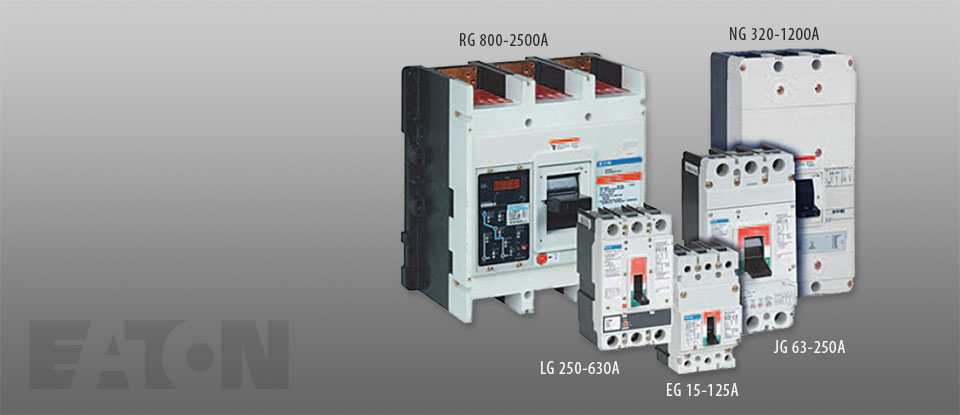
In low voltage distribution systems, there are many varied applications of molded case circuit breakers. Eaton offers the most comprehensive family of molded case circuit breakers in the industry.
This section of circuit breakers includes:
- Thermal-magnetic trip breakers
- Electronic rms trip breakers
- Molded case switches
- Motor circuit protectors
- Current limiting breakers
- Special application breakers
Modified Breakers
Eaton breakers can be ordered with internal accessories installed. These modified breakers will be subject to an addition charge.
Special Calibration
Special non-UL listed calibrations are available for certain ambient temperatures other than 40°C and for frequencies other than 50/60 Hz or DC. Reduced interrupting ratings will apply for 400 Hz applications.
- Add suffix H01 to breaker catalog number for 400 Hz rating
50°C Calibration
Note: Breakers equipped with electronic trip units can operate reliably in ambient temperatures of 50°C. Add suffix “V3” to NG MCCBs to remove standard 40°C labeling.
Add suffix “V” to catalog number for complete thermal magnetic breaker when ordering listed ampere ratings for breakers to be used in 50°C ambients. 50°C ambient MCCBs are not UL listed.
Moisture-Fungus Treatment
All Eaton circuit breaker cases are molded from glasspolyester, which does not support the growth of fungus. Any parts that are susceptible to the growth of fungus will require special treatment.
Order by description.
- Add suffix J01 to breaker part number
Freeze-Tested Circuit Breakers
The circuit breakers may be ordered with freeze testing. This option uses special lubrication and mechanical operation is verified at –40°C.
- Add suffix F01 to part number –57°F, F02 –30°F
Marine Applications
E- to R-Framed circuit breakers can be supplied to meet the following marine specifications:
- U.S. Coast Guard CFR 46; ABS—American Bureau of Shipping; IEEE 45; DNV; and Lloyds
These specifications generally require molded case circuit breakers to be supplied with 50°C ambient, and plug-in adapter kits. When plug-in adapter kits are used, no terminals need be supplied (switchboard applications).
Circuit breakers can also be supplied to meet UL 489 Supplement SA (Marine use) and UL 489 Supplement SB (Naval Use).
UL 489 Supplement SA applies to vessels over 65 feet (19.8m) in length.
Requirements include 40°C ambient calibration, special labeling, and no use of aluminum conductors or terminals. (No 50°C.)
- Add suffix H08
Or you can choose to add 50°C ambient but then there is no “UL” mark.
- Add suffix VH08
UL 489 Supplement SB requires partial 50°C ambient calibration, vibration testing, special nameplating and no use of aluminum conductors or terminals. Eaton chooses to always fully calibrate to 50°C ambient. (“Naval” labeled per UL but no “UL” mark due to 50°C label.)
- Add suffix VH09
Certified Test Reports
Eaton breakers can be ordered with certified test reports at the time of order entry. Test report documents the thermal and magnetic or electronic tripping characteristics of the individual breaker. Breaker and test report must be ordered together. Add suffix 12 to breaker catalog number and enter separate line item on order for certified test report.
Standards and Certifications
Molded case circuit breakers are designed to conform with the following standards:
- Underwriters Laboratories Inc., Standard UL 489, molded case circuit breakers and circuit breaker enclosures
- National Electrical Manufacturers Association (NEMA) Standards Publication No. AB1-1993, molded case circuit breakers
- Australian Standard AS 2184, molded case circuit breakers
- British Standards Institution Standard BS 4752: Part 1, switchgear and control gear Part 1: circuit breakers
- Canadian Standards Association (CSA) Standard C22.2 No. 5, service entrance and branch circuit breakers
- International Electrotechnical Commission Recommendations IEC 60947-2, circuit breakers
- Japanese T-Mark Standard molded case circuit breakers
- South African Bureau of Standards, Standard SABS 156, Standard Specification for molded case circuit breakers
- Swiss Electro-Technical Association Standard SEV 157-1, safety regulations for circuit breakers
- Verband Deutscher Elektrotechniker (Association of German Electrical Engineers) Standard VDE 0660, low voltage switchgear and control gear, circuit breakers
- Union Technique de l’Electricite Standard NF C 63-120, low voltage switchgear and control gear circuit breaker requirements
Conformance with these standards satisfies most local and international codes, assuming user acceptability and simplified application.
Molded case circuit breakers equal or exceed Federal Specification Classification W-C-375b requirements for the particular class associated with the circuit breaker frame being considered.
Open breakers do not have service entrance ratings. Service entrance rating is part of the enclosure.
Internal Accessories
Alarm Lockout
The alarm switches operate when the circuit breaker is tripped by a short circuit or overcurrent, but also when it is tripped by a shunt trip or undervoltage release.
Auxiliary Switches
Auxiliary switches are used for signaling and control purposes.
Shunt Trips
The shunt trip is used for remote tripping.
The coil of the shunt trip is rated only for short-time operation.
It is not permissible with the circuit breaker open to apply a continuous opening command to the shunt trip in order to prevent the breaker from closing. This means that interlocking circuits with continuous commands may not be set up with shunt trips.
Undervoltage Releases
The circuit breaker cannot be closed until the undervoltage release is energized. If the release is not energized, the circuit breaker can only perform an idle switching operation.
Frequent idle switching actions should be avoided as they shorten the endurance of the circuit breaker.
Cause of Trip Display/Remote Mount Cause of Trip Display
The Cause of Trip Display can be field-installed on any Digitrip RMS 310+ trip unit. The device provides breaker information through an LCD screen, such as cause of trip, phrase current, ground current and low loads. The display is ideal for troubleshooting common trips such as ground fault, long delay, and instantaneous/short delay. The DIGIVIEW version will provide a local display at the breaker without additional wiring by connecting directly onto the trip unit. The DIGIVIEWR06 version has a 6 foot cable that allows users to mount the display on the outside of an enclosure door and connect to the trip unit that is contained inside the enclosure.
Cause of Trip Display/ Remote Mount Cause of Trip Display
| Part Number |
| DIGIVIEW |
| DIGIVIEWR06 |
Cause of Trip LED Module
The Cause of Trip LED Module can be field-installed on any Digitrip RMS 310+ trip unit. The device provides a cause of trip indication via LED. The Cause of Trip LED Module connects directly onto the trip unit. When the breaker trips, the module indicates the cause of trip (long delay, short delay, instantaneous and ground) via LED indication. The module is reset after the breaker is reset.
Cause of Trip LED Module
| Part Number |
| TRIP-LED |
External Accessories and Test Kit
External Accessories
| Description | Fit Type |
Frame EG |
JG | LG | NG | RG |
| Non-padlockable handle block | Field | EFHB | — | — | LKD4 | — |
| Padlockable handle block | Field | EFPHB | — | — | — | — |
| Padlockable handle block off-only |
Field | EFPHBOFF | FJPHBOFF | LBHPOFF | — | — |
| Padlockable handle lock hasp | Field | EFPLK | FJPHL | LPHL | PLK5 | HLK6 |
| Padlockable handle lock hasp off-only | Field | EFPHLOFF | FJPHLOFF | LPHLOFF | PLK55OFF | HLK6OFF |
| Kirk key interlock kit(1)(2) | Field | — | KYKJG | KYKLG | KYK4 | KYK6 |
| Castell key interlock kit(2)(3) | Field | — | CTKJG | CTKLG | CTK4 | CTK6 |
| Slide bar interlock(4) | Field | EFSBI | FJSBI | LGSBI | SBK5 | — |
| Walking beam interlock(4) | Three-pole | EG3WBI | JG3WBI | LG3WBI | WBL5 | WBL6 |
| Four-pole | EG4WBI | JG4WBI | LG4WBI | WBL5 | — | |
| Electrical operator 5 | 120 Vac | MOPEG240C | MOPJG120C | MOPLG120C | EOP5T07 | EOP6T08K |
| 240 Vac | MOPEG240C | MOPJG240C | MOPLG240C | EOP5T11 | EOP6T11K | |
| 24 Vdc | MOPEG48D | MOPJG24D | MOPLG24D | EOP5T21 | — | |
| 48 Vdc | MOPEG48D | — | — | EOP5T22 | EOP6T21K | |
| 125 Vdc | MOPEG120C | MOPJG120C | MOPLG120C | EOP5T26 | — | |
| 220 Vdc | — | MOPJG240C | MOPLG240C | — | — | |
| 250 Vdc | — | MOPJG240C | MOPLG240C | — | — | |
| Plug-in adapters | Three-pole | PAD3E | PAD3J | PAD3L | PAD53 | — |
| Four-pole | PAD4E | PAD4J | PAD4L | — | — | |
| Rear connecting studs(6) | Field | EFRCSDL | FJRCSDL | LRCS3WK (3P} | — | — |
| EFRCSDS | FJRCSDS | LRCS4WK (4P} | — | — | ||
| EFRCSWL | FJRCSWL | — | — | — | ||
| EFRCSWS | FJRCSWS | — | — | — |
Test Kit
| Description | Fit Type | EG | JG | LG | NG | RG |
| Electronic portable test kit | 120V | N/A | MTST120V | MTST120V | MTST230V(7) | MTST230V(7) |
| 230V | N/A | MTST230V | MTST230V | MTST230V(7) | MTST230V(7) |
NOTES:
(1) Provision only.
(3) Castell bolt mounting hole must be 10 mm.
(4) Requires two breakers.
(5) Contact Eaton for availability of operators for EG- and NG-Frames before December 2004.
(6) D = Imperial threads UL, W = metric threads IEC, L = long studs, S = short studs.
(7) MTST230V applies to 100–230 Vac, resulting in the same catalog number for 120V and 230V.
Field Fit Kit Part Numbers
Alarm Lockout
| Description | Pole Location |
EG, JG & LG | NG | RG(1) |
| Make/Break | Left | — | A1L5LPK | — |
| Right | ALM1M1BEPK(2) | A1L5RPK | A1L6RPK | |
| 2 Make/2 Break | Left | — | A2L5LPK | — |
| Right | ALM2M2BEPK(3) | A2L5RPK | A2L6RPK |
Auxiliary Switch
| Description | Pole Location |
EG, JG & LG | NG | RG(1) |
| 1A, 1B | Left | — | A1X5PK | — |
| Right | AUX1A1BPK | A1X5PK | — | |
| 2A, 2B | Left | — | A2X5PK | — |
| Right | AUX2A2BPK | A3X5LPK | A2X6RPK | |
| 3A, 3B | Left | — | A3X5LPK | — |
| Right | — | A3X5RPK | — | |
| 4A, 4B | Left | — | — | — |
| Rigt | — | — | A4X6RPK |
Auxiliary Switch/Alarm Lockout
| Description | Pole Location |
EG, JG & LG | NG | RG(1) |
| — | Left | — | AA115LPK | — |
| Right | AUXALRMEPK(4) | AA115RPK | — |
Shunt Trip—Standard
| Description | Pole Location |
EG, JG & LG | NG | RG(1) |
| 48–60 Vac | Left | SNT060CPK | SNT5LP05K | — |
| Right | — | — | SNT6P05K | |
| 10–240 Vac | Left | SNT120CPK | SNT5LP11K | — |
| Right | — | — | SNT6P11K | |
| 380–600 Vac | Left | SNT480CPK(6) | — | — |
| Right | — | — | — | |
| 220–250 Vdc or 380–440 Vac | — | SNT5LP14K | SNT6P14K | |
| 480–600 Vac | — | SNT5LP18K | SNT6P18K | |
| 12 Vdc | Left | SNT012CPK | — | — |
| Right | — | — | — | |
| 24 Vac/dc | Left | SNT060CPK | SNT5LP03K | — |
| Right | — | — | — | |
| 48–60 Vdc | Left | SNT060CPK | SNT5LP23K | — |
| Right | — | — | SNT6P23K | |
| 110–125 Vdc | Left | SNT125DPK | SNT5LP26K | — |
| Right | — | — | SNT6P26K | |
NOTES:
(1) All accessories mount in the RH cavity which will accept one each of shunt trip, UVR, auxiliary switch and alarm switch.
(2) Part number for JG and LG is ALM1M1BJPK.
(3) Part number for JG and LG is ALM2M2BJPK.
(4) Part number for JG and LG is AUXALRMJPK.
(5) LH cavity not available for EG frame with earth leakage module.
(6) 380–600 Vdc, 50/60 Hz.
Shunt Trip—Low Energy
| Description | Pole Location |
EG, JG & LG | NG | RG(1) |
| — | Left | — | LST5LPK | — |
| Right | — | — | LST6RPK |
Undervoltage Release Mechanism
| Description | Pole Location |
EG, JG & LG(3) | NG | RG(1) |
| 110—127 Vac | Left | UVR120APK | UVH5LP08K | — |
| Right | — | — | UVH6RP08K | |
| 208—240 Vac | Left | UVR240APK | UVH5LP11K | — |
| Right | — | — | UVH6RP11K | |
| 24 Vdc | Left | UVR024DPK | UVH5LP21K(2) | — |
| Right | — | — | UVH6RP21K(2) | |
| 24 Vac | Left | UVR024APK | UVH5LP21K(2) | — |
| Right | — | — | UVH6RP21K(2) | |
| 48—60 Vdc | Left | UVR048DPK | UVH5LP23K | — |
| Right | — | — | UVH6RP23K | |
| 48—60 Vac | Left | UVR048APK | UVH5LP05K | — |
| Right | — | — | UVH6RP05K | |
| 120 Vdc | Left | UVR125DPK | UVH5LP26K | — |
| Right | — | — | UVH6RP26K | |
| 220—250 Vdc | Left | UVR250DPK | UVH5LP28K | — |
| Right | — | — | UVH6RP28K | |
| 380—500 Vac | Left | UVR480APK | UVH5LP29K | — |
| Right | — | — | UVH6RP29K | |
| 525—600 Vac | Left | UVR600APK | — | — |
| Right | — | — | — | |
| 12 Vdc | Left | — | UVH5LP20K | — |
| Right | — | — | UVH6RP20K | |
| 12 Vac | Left | — | UVH5LP02K | — |
| Right | — | — | UVH6RP02K |
NOTES:
(1) All accessories mount in the RH cavity which will accept one each of shunt trip, UVR, auxiliary switch and alarm switch.
(2) 24 Vdc only use UVH5LP03K (NG) UVH6RP03K (RG) for 24 Vac.
(3) LH cavity not available for EG frame with earth leakage module.