Eaton Series-C Molded Case Circuit Breakers External Accessories

External Accessories
Product Overview
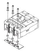
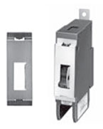
End Cap Kit
The end cap kit slides onto the line or load conductor of the circuit breaker and acts as a threaded adapter for the conductor to accept a ring terminal or other bolt-on connector. The end cap kit is available with English and metric thread sizes. (Field installation only.) Listed per UL File E7819.
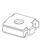
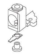
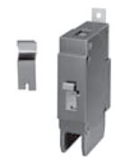
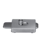
Keeper Nut
The keeper nut slides onto the line or load conductor of the circuit breaker and acts as a threaded adapter for the conductor to accept a ring terminal or other bolt-on connector. The keeper nut is available with English and metric thread sizes. Screws and washers are supplied by customer. (Field installation only.) Listed per UL File E7819.
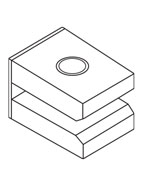
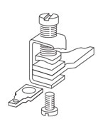
J-Frame Plug Nut
The plug nut is used in applications where screwconnected ring-type terminals are preferred to connect cables to circuit breaker conductors. The plug nut is press-fit into the opening in the circuit breaker terminal conductor. Screws and washers are supplied by customer.
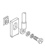
Terminal Adapter
Control Wire Terminal Kit
The control wire terminal kit provides a means to tap off control power from a main disconnect, using the provided male end of a quick disconnect.
For use with steel or stainless steel terminals only.
Note: Terminal Kits contain one terminal for each pole and one terminal cover.
Multiwire Connectors
Eaton’s field-installed multiwire connectors for the load side (OFF) end terminals are used to distribute the load from the circuit breaker to multiple devices without the use of separate distribution terminal blocks.
Multiwire lug kits include mounting hardware, insulators and tin-plated aluminum connectors to replace three mechanical load lugs. UL listed as used on the load side (OFF) end.
Terminal Shields
Terminal shields provide protection against accidental contact with live line side terminations. Terminal shields are fabricated from high dielectric insulating material and fasten over the front terminal access openings. Small openings in the shields provide limited access to the terminals for tightening connectors. (Field installation only.)
Rear Fed Terminals
Rear fed terminals allow the cable to connect to the breaker from the back instead of the top. Terminal shields or interphase barriers are included with each rear fed terminal kit (depending on frame size). When catalog number starts with a 3, it indicates a kit with three terminals in each kit. Part number beginning with a TA indicates one terminal.
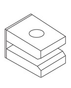
Terminal End Covers
The terminal end covers are designed for use in motor control center applications where, because of confined spaces, line side conductors are normally custom fitted. The molded end covers are made of high dielectric glasspolyester and slide over the line ends of the circuit breaker. Close fitting conductor openings are molded into the end covers. The end cover and circuit breaker case fit together to form terminal compartments that isolate discharged ionizing gases during circuit breaker tripping. Terminal end covers are available with two conductor opening diameters, 0.25-inch (6.4 mm) and 0.41- inch (10.4 mm), and are listed per UL File E7819. (Field installation only.)
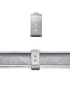
Interphase Barriers
The interphase barriers provide additional electrical clearance between circuit breaker poles for special termination applications. The barriers are high dielectric insulating plates that are installed in the molded slots between the terminals. (Field installation only.) Two per package.
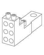
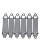
Base Mounting Plate
Suitable for mounting six single-pole circuit breakers.
DIN Rail Adapter
For use with standard 35 mm DIN rail such as, 35 x 7.5 or 35 x 15 mm per DIN EN50022.
Adapter mounting screws included are for use with twoand three-pole circuit breakers. Adapters for singlepole circuit breakers clip into the base molding.
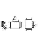
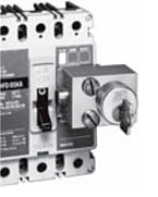
Key Operated Attachment
Lock Dog (Non-Padlockable)
Non-Padlockable Handle Block
The non-padlockable handle block secures the circuit breaker handle in either the ON or OFF position. (Trip-free operation allows the circuit breaker to trip when the handle block holds the circuit breaker handle in the ON position.) The device is positioned over the circuit breaker handle and secured by a setscrew to deter accidental operation of the circuit breaker handle. Listed per UL File E7819. (Field installation only.)
Padlockable Handle
Padlockable Handle Lock
The device is positioned in the cover opening to prevent handle movement. Will accommodate one 5/16-inch (8 mm) padlock.
Snap-on Padlockable Handle Lock Hasp
The snap-on padlockable handle lock allows the handle to be locked in the OFF or ON position. (Trip-free operation allows the circuit breaker to trip when the handle lock holds the circuit breaker handle in the ON position.) This device was designed for use on the single-pole circuit breaker, but may be used on one-, two-, threeand four-pole styles. The handle lock snaps onto the escutcheon area of the handle with an optional retaining screw for added secureness. The handle lock will accommodate one padlock with a 1/4-inch (6.4 mm) shackle. Listed per UL File E7819. (Field installation only.)
Padlockable Handle Lock Hasp
The padlockable handle lock hasp allows the handle to be locked in the ON or OFF position. (Trip-free operation allows the circuit breaker to trip when the handle lock holds the circuit breaker handle in the ON position.) The hasp mounts on the circuit breaker cover within the trimline. The cover is predrilled on both sides of the operating handle so that the hasp can be mounted on either side of the handle. The hasp will accommodate up to three padlocks with 1/4-inch (6.4 mm) shackles, one per circuit breaker. Listed per UL File E7819. (Field installation only.)
Cylinder Lock
The cylinder lock internally blocks the trip bar in the tripped position to prevent the circuit breaker from being switched to ON. The cylinder lock is factory installed in the left pole only of the circuit breaker cover. Other internally mounted accessories cannot be installed in the same pole as the cylinder lock. (Factory installation only.)
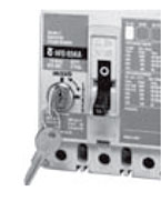
Key Interlock Kit (Lock Not Included)
The key interlock is used to externally lock the circuit breaker handle in the OFF position. When the key interlock is locked, an extended deadbolt blocks movement of the circuit breaker handle. Uniquely coded keys are removable only with the deadbolt extended. Each coded key controls a group of circuit breakers for a given specific customer installation.
The key interlock assembly is Underwriters Laboratories listed for field installation under UL File E7819 and consists of a mounting kit and a purchaser supplied deadbolt lock. The mounting kit comprises a mounting plate, which is secured to the circuit breaker cover in either the left- or right-pole position, key interlock mounting screws, and a wire seal. Specific mounting kits are required for individual key interlock types.
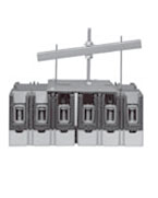
Sliding Bar Interlock
The sliding bar interlock provides mechanical interlocking between two adjacent three-pole circuit breakers. It is installed on the enclosure cover between the circuit breakers. When the sliding bar interlock handle is moved from one side to the other, a bar extends to alternately block movement of the circuit breaker handles and prevents both circuit breakers from being switched to ON at the same time. Sliding bar interlocks are not UL listed. (Field installation only.)
Walking Beam Interlock
The walking beam Interlock provides mechanical interlocking between two adjacent circuit breakers of the same pole configuration. The walking beam interlock mounts on a bracket behind and between the circuit breakers. A plunger on each end of the beam is inserted through an access hole in the back plate and base of each circuit breaker. The walking beam interlock prevents both circuit breakers from being switched ON at the same time. If a walking beam interlock is installed, the wiring troughs in the back of the circuit breaker case are blocked by the plungers and cannot be used for cross wiring. Factory modified circuit breakers are required for this application. UL File E38116.
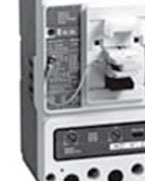
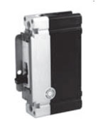
Electrical Operator
The electrical (solenoid) operator is a single solenoid mechanism that enables local and remote circuit breaker ON, OFF, and reset switching. The electrical operator is mounted on the circuit breaker cover within the trimline of the circuit breaker. The electrical operator uses a unique bi-stable latch that allows the device to operate using one solenoid. The accessory provides high-speed switching with a maximum operating time of 5 cycles (80 mS), making it suitable for generator synchronizing applications.
Means are provided for remote electrical operation and for local manual operation. A special slide includes provisions for padlocking the circuit breaker handle in the OFF position. The slide will accept three padlock shackles with a maximum diameter of 1/4-inch (6.4 mm) each. An interlock electrically disconnects the solenoid when the electrical operator cover is removed. The rating data tables provide electrical rating data for the electrical (solenoid) operator.
The electrical (motor) operator allows the circuit’s breaker to be opened, closed or reset remotely. It also has a lock-off capability and provisions for manual operation.
The electrical (motor) operator contains a reversible motor connected to a ball screw. The ball screw drives the circuit breaker handle. Limit switches and relays are used to control the motor.
Plug-In Adapters
Plug-in adapters simplify installation and front removal of circuit breakers. Individual line and load plug-in adapters are available for rear connection applications on two-, three-, and four-pole circuit breakers. Common mounting plates for lineand load-end adapters are available.
One plug-in adapter kit is required for line-end and one for load-end.
Plug-in adapters are UL approved unless otherwise noted.
Rear Connecting Studs
Rear connecting studs are available in several sizes to accommodate specific fixedmounted circuit breaker applications.
Each rear connecting stud assembly consists of one stud and one tube. To maintain proper clearances between poles, select alternate long and short stud assemblies for circuit breakers with more than one pole. One assembly is required for line-end and one for load-end of each pole. Tubes must be ordered separately. Connecting studs are available only with English thread sizes.
Note: Not UL listed.
Panelboard Connecting Straps
Panelboard connecting straps are used to connect the circuit breaker terminals to the panelboard bus. The panelboard connecting straps are available with various ratings for outside and center poles. (Field installation only.)
Panelboard connecting straps are available to meet the needs of most standard panelboard applications. Style numbers for mounting brackets for CDP panelboard installations are also included.
Note: Not UL listed. Refer to panelboard manufacturer for compatibility.
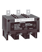
ype LFD Current Limiter
The LFD current limiter is an accessory that bolts to the load end of a standard FDB or FD thermal-magnetic circuit breaker, providing 200,000A interrupting capacity at up to 600 Vac. LFD current limiters for thermal-magnetic and electronic circuit breakers are listed with Underwriters Laboratories under File E47239.
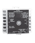
Ground Fault Alarm Unit
The ground fault alarm unit is a remotely mounted device with a combination indicating light/test button that will light when the breaker trips or alarms on ground fault. The ground fault alarm unit requires a separate 120 Vac power source to power the light and the internal relay, which has 1NO and 1NC contacts for remote indication. The ground fault alarm unit can be panel mounted for ordering with an optional face mounting bracket. For use on Digitrip 310 only, K- through N-Frame.
IQ Energy Sentinel
The IQ Energy Sentinel is a highly accurate, microprocessor-based, breaker-mounted device designed to monitor power and energy readings. It represents an alternative to watt meters, watt-hour meters, and watt demand meters. Key advantages include savings in space, lower installation costs, and remote monitoring capability.
The IQ Energy Sentinel mounts on the load side of a Series C F-Frame (150 ampere) circuit breaker. It can be applied on threephase, four-wire systems, or single-phase, three-wire systems with voltage connected through Phases A and C.
TPotential Transformer Module
The potential transformer module is required for the Digitrip OPTIM 1050 to provide a voltage input to allow the trip unit to monitor power and energy as well as power factor. The potential transformer module is a 6 VA transformer with a primary voltage input of up to 600 volt line to line. Three 0.1 ampere fuses are provided on the primary of the transformer and can be used for isolation purposes during dielectric testing. The device is normally panel mounted and can feed up to 16 OPTIM trip units.
Solid-State (Electronic) Portable Test Kit
The solid-state (electronic) portable test kit provides verification of performance of all ratings of Digitrip 310 electronic trip units installed in circuit breakers while in service under varying load and/or phase imbalance. The test kit operates on 120-volt, 50/60 Hz power; it includes complete instructions and test times for testing long time, short time/instantaneous operation and optional ground fault operation of the circuit breaker.
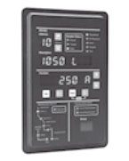
Breaker Interface Module (BIM)
The Breaker Interface Module (BIM) is a panel mounted user interface device that is mounted on the front of an electrical assembly or at a remote location. The BIM is used to access, configure, test and display information for OPTIM trip units and other devices. The BIM consists of four display windows, eight function buttons, 18 LEDs, and a graphical time/current curve to provide breaker status, operational information, protection status and energy monitoring. A 24 Vdc power supply is required to provide power to the BIM. This is supplied by the switchboard builder to Eaton’s specifications. The BIM is a member of Eaton’s PowerNet family of communicating devices that connects OPTIM trip units, Digitrip RMS 810/910 trip units and energy sentinels as a subnetwork system. The BIM can also be connected to a main network via a PONI module to PowerNet software.
Digitrip OPTIMizer
The Digitrip OPTIMizer is a hand-held programmer that is used to access, configure, test and display information from OPTIM trip units. The OPTIMizer plugs into the front of an OPTIM trip unit via an eight-pin telephone jack and is powered by a nine-volt battery or the auxiliary power module. One highlighted feature is the “Copy” and “Download” commands.
Setting up multiple OPTIM trips can be finished in minutes and with no errors. An Auxiliary Power Module connection provides a trip test when control power is not present at the breaker. The OPTIMizer is supplied as a standard package to include the programmer, the eightpin connection cord, battery and carrying case. The auxiliary power module is optional.
Auxiliary Power Module
The auxiliary power module is a power supply requiring 120 Vac input at 50 or 60 Hz that provides a 32 Vdc output. The auxiliary power module provides control power for testing an OPTIM trip unit when other means of control power is not available or for continuous OPTIMizer operation versus temporary with a battery. The auxiliary power module connects into the top of the Digitrip OPTIMizer via a keyed receptacle. The main application for the auxiliary power module would be for the testing of a standalone non-communicating OPTIM breaker that ordinarily would not have control power.
Cause of Trip Display/Remote Mount Cause of Trip Display
The Cause of Trip Display can be field-installed on any Digitrip RMS 310+ trip unit. The device provides breaker information through an LCD screen, such as cause of trip, phrase current, ground current and low loads. The display is ideal for troubleshooting common trips such as ground fault, long delay, and instantaneous/short delay. The DIGIVIEW version will provide a local display at the breaker without additional wiring by connecting directly onto the trip unit. The DIGIVIEWR06 version has a 6 foot cable that allows users to mount the display on the outside of an enclosure door and connect to the trip unit that is contained inside the enclosure.
Cause of Trip LED Module
The Cause of Trip LED Module can be field-installed on any Digitrip RMS 310+ trip unit. The device provides a cause of trip indication via LED. The Cause of Trip LED Module connects directly onto the trip unit. When the breaker trips, the module indicates the cause of trip (long delay, short delay, instantaneous and ground) via LED indication. The module is reset after the breaker is reset.
Note: The OPTIMizer can work off of 32 Vdc control power, although 24 Vdc is the standard on OPTIM breakers.
Product Selection
Termination Hardware—End Cap Kit
End Cap Kit
| Thread Type | Thread Size | Part Number |
| Two-Pole F-Frame (225A) | ||
| Imperial | 10–32 | KPEK12 |
| Metric | M–5 | KPEKM12 |
| Three-Pole F-Frame (225A) | ||
| Imperial | 10–32 | KPEK1 |
| Metric | M–5 | KPEKM1 |
| Four-Pole F-Frame (225A) | ||
| Imperial | 10–32 | KPEK14 |
| Metric | M–5 | KPEKM14 |
| Three-Pole J-Frame | ||
| Imperial | 0.312–18 | KPEK2 |
| Metric | M–8 | KPEKM2 |
| Four-Pole J-Frame | ||
| Imperial | 0.312–18 | KPEK24 |
| Metric | M–8 | KPEKM24 |
| Three-Pole K-Frame | ||
| Imperial | 0.312–18 | KPEK3 |
| Metric | M–8 | KPEKM3 |
| Four-Pole K-Frame | ||
| Imperial | 0.312–18 | KPEK34 |
| Metric | M–8 | KPEKM34 |
| Three-Pole L-Frame | ||
| Imperial | 0.312–18 | KPEK4 |
| Metric | M–8 | KPEKM4 |
| Four-Pole L-Frame | ||
| Imperial | 0.312–18 | KPEK44 |
| Metric | M–8 | KPEKM44 |
Termination Hardware—Keeper Nut
F-Frame Keeper Nut
F-Frame Keeper Nut
| Thread Type | Thread Size | Part Number Package of 12 (Priced Individually) |
| Imperial | 10-32 | KPR1A |
| Metric | M-5 | KPR1AM |
F-Frame Keeper Nut
K-Frame Keeper Nut
| Thread Type | Thread Size | Line/Load End |
Part Number Package of 12 (Priced Individually) |
| Imperial | 0.375–16 | Line | KPR3A |
| Load | KPR3B | ||
| Metric | M-8 | Line | KPR3AM |
| Load | KPR3BM |
NOTE:
L-, M-, N-Frames not required. Terminals are threaded.
Termination Hardware
J-Frame Plug Nut
J-Frame
Plug Nut
| Thread Type | Thread Size | Part Number Package of 6 |
| Imperial | 0.250–20 | PLN2 |
| Metric | M-6 | PLN2M |
K-Frame Terminal Adapter(1)
K-Frame Terminal Adapter
| Line/Load End | Part Number |
| Line and load | TAD3 |
F-Frame Ordering Information
Terminals must be ordered separately. Priced individually.
F-Frame Control Wire Terminal Kit(2)
F-Frame Kit
| Description | Maximum Amperes | Part Number |
| Package of 12 control wire terminal tangs. | 150 | FCWTK |
| 225 | FCWTK225 |
J- and K-Frame Ordering Information
Terminals must be ordered separately. Priced individually.
J- and K-Frame Control Wire Terminal Kit
F-Frame Kit
| Description | Part Number |
| Package of 12 control wire terminal tangs. | KCWTK |
L-Frame Control Wire Terminal Kit
| AWG Wire Range/Number Conductors |
Metric Wire Range mm2 |
Part Number |
| Al/Cu 3/0–350 kcmil (2) |
95–150 | TA602LDCW(3) |
| Cu 250–350 kcmil (2) |
120–250 | T602LDCW(3) |
| Al/Cu 400–500 kcmil (2) |
185–240 | 2TA603LDKCW(4)(5) |
| Al/Cu 400–500 kcmil (2) |
185–240 | 3TA603LDKCW(4)(5) |
| Al/Cu 400–500 kcmil (2) |
185–240 | 4TA603LDKCW(4)(5) |
NOTES:
(1) K-Frame terminal adapter for use in replacing LB/DA breakers.
(2) Not for use with T250KB terminals.
(3) Individually packed.
(4) Terminal kits contain one terminal for each pole and one terminal cover.
(5) Two-pole kit.
(6) Three-pole kit.
(7) Four-pole kit.
G-Frame Control Wire Terminal
| Description | Part Number | Part Number |
| Control wire terminal (kit of 12) | 5652B38G01 | GCWTK |
Multiwire Connectors Ordering Information (Package of 3)
Multiwire Connectors
| Maximum Amperes |
Wires per Terminal |
Wire Size Range AWG Cu |
Kit Part Number(1) |
| G-Frame(2) | |||
| 100 | 3 | 14-2 | 3TA100G3K |
| 6 | 14-6 | 3TA100G6K | |
| F-Frame | |||
| 225 | 3 | 14-2 | 3TA150F3K |
| 6 | 14-6 | 3TA150F6K | |
| J-Frame | |||
| 250 | 3 | 14-2 | 3TA250J3K |
| 6 | 14-6 | 3TA250J6K | |
| K-Frame | |||
| 400 | 3 | 14-2/0 | 3TA400K3K |
| 6 | 14-3 | 3TA400K6K | |
Rear Fed Terminals
| Frame | Maximum Amperes |
Wire Size Range AWG Cu |
Kit Part Number(1) |
| FD | 150 | 14-4/0 | TA150FDRF |
| 150 | 14-4/0 | 3TA150FDRF | |
| 225 | 6–300 kcmil | TA225FDRF | |
| 225 | 6–300 kcmil | 3TA225FDRF | |
| KD | 400 | 250–500 kcmil | TA350KRF |
| 400 | 250–500 kcmil | 3TA350KRF | |
| MDL | 800 | 3/0 MAX (3) | TA800MDLRF |
| 800 | 3/0 MAX (3) | 3TA800MDLRF |
NOTES:
(1) When catalog number starts with a 3, it indicates a kit with three terminals in each kit. Part number beginning with a TA indicates one terminal.
(2) GD breakers require special tapping for multiwire lugs, as described in the IL or use with standard aluminum collars.
Base Mounting Hardware
Ordering Information
Hardware for surface mounting of circuit breakers is supplied only on request. Hardware consists of mounting screws and lockwashers. Order hardware for circuit breaker pole configurations as required.
Mounting Hardware
| Screw Length in Inches (mm) | Part Number |
| G-Frame | |
| 0.138–32 x 2.63 (3.5 x 66.7 mm) Std. | 624B375G23 |
| 0.138–32 x 3.00 (3.5 x 76.2 mm) | 8703C80G05 |
Imperial Thread Mounting Hardware
| Number of Poles | Description | Type of Mounting | Part Number |
| F-Frame | |||
| 1 | 0.164-32 x 3.188-inch pan-head steel screws, lockwashers and clamps | Individual | 624B375G01 |
| Group(1) | 624B375G02 | ||
| 2 | 0.164-32 x 1.5-inch pan-head steel screws and lockwashers | Individual | 4218B80G01 |
| 3, 4 | 0.164-32 x 1.5-inch pan-head steel screws and lockwashers | Individual | BMH1 |
| J-Frame | |||
| 2, 3, 4 | 0.250-20 x 2.75 inch pan-head steel screws and lockwashers | Individual | BMH2 |
| K-Frame | |||
| 2, 3, 4 | 0.250-20 x 1.5 inch pan-head steel screws and lockwashers | Individual | BMH3 |
| L-Frame | |||
| 2, 3, 4 | 0.250-20 x 1.5 inch filister-head steel screws and lockwashers and flat washers | Individual | BMH4 |
| M-Frame | |||
| 2, 3 | 0.3125-18 x 1.25 inch filister-head steel screws and lockwashers and flat washers | Individual | BMH5 |
| N-Frame | |||
| 2, 3, 4 | 0.3125-18 x 1.25 inch pan-head steel screws and lockwashers | Individual | BMH5 |
| R-Frame | |||
| Supplied by customer | |||
Metric Thread Mounting Hardware
| Number of Poles | Description | Type of Mounting | Part Number |
| F-Frame | |||
| 1 | M4–0.7 x 80 mm pan-head steel screws, lockwashers, and clamps | Individual | 4218B80G09 |
| Group(1) | 4218B80G10 | ||
| 2 | M4–0.7 x 38 mm pan-head steel screws and lockwashers | Individual | 4218B80G11 |
| 3, 4 | M4–0.7 x 38 mm pan-head steel screws and lockwashers | Individual | BMH1M |
| J-Frame | |||
| 2, 3, 4 | M6–0.7 x 70 mm pan-head steel screws and lockwashers | Individual | BMH2M |
| K-Frame | |||
| 2, 3, 4 | M6–0.7 x 38 mm pan-head steel screws and lockwashers | Individual | BMH3M |
| L-Frame | |||
| 2, 3, | — | Individual | BMH4M |
| M-Frame | |||
| 2, 3 | — | Individual | BMH5M |
| N-Frame | |||
| 2, 3 | — | Individual | BMH5M |
| R-Frame | |||
| Supplied by customer | |||
NOTES:
(1) One set of hardware for two circuit breakers.
Terminal Shields
G-Frame Terminal Shield
| Number Units in Package | Part Number |
| 10 | GTSK3 |
F-Frame Terminal Shield
F-Frame
| Number of Poles |
Location | Standard
(Package of 10) (Priced Individually) |
Special—For Use
When Electrical Operator is Mounted on Circuit Breaker |
| 1 | Line | 625B229G06 | — |
| 2 | Line | 625B229G07 | — |
| 3 | Line | 625B229G08 | 4210B95G01 |
| 4 | Line | 625B229G09 | 4210B95G02 |
J-Frame Terminal Shield
J-Frame
| Number of Poles |
Location | Part Number (package of 10) |
| 2, 3 | Line End | 1266C07G01 |
| 4 | Line End | 6631C01G01 |
| 2, 3 | Line End | 6641C16G01 |
| 4 | Line End | 6641C16G02 |
K, L, M & N-Frame Terminal Shield
K-Frame
| Frame Size | Number of Poles |
Location | Part Number (package of 10) |
| K | 2, 3 | Line End | TS33LN |
| 4 | Line End | TS34LN | |
| 3 | Line End | TS33LD | |
| L | — | — | 314C420G05 |
| M | — | — | 208B966G01 |
| N | — | — | NTS3K |
Terminal End Covers
F-Frame Terminal End Covers
F-Frame
| Conductor
Opening Diameter in Inches (mm) |
Part Number |
| 0.25 (6.35 mm) | TEC1 |
| 0.41 (10.41 mm) | TEC2 |
Interphase Barriers
Interphase Barriers (2 per package)
Interphase Barrier
| Frame | Part Number |
| F | IPB1 |
| J, K | IPB2 |
| L | IPB3 |
| M | IPB4 |
| N | IPB5 |
Base Mounting Plate
Base Mounting Plate G-Frame GD/GHC
Base Mounting Plate
| Number of Units in Package |
Part Number |
| 1 | 207B513G01 |
DIN Rail Adapter
DIN Rail Adapter G-Frame GD/GHC
DIN Rail Adapter
| Number of Poles | Number of Units in Package |
Part Number |
| 1, 2 | 10 | 1225C79G01 |
| 3 | 10 | 1225C79G02(1) |
Key Operated Attachment
Key Operated Attachment G-Frame GD/GHC
Key Operated Attachment
| Number of Units in Package |
Part Number |
| 10 | GKOA |
Lock Dog (Non-Padlockable)
Lock Dog (Non-Padlockable) G-Frame GD/GHC/GHB/GMCP
Key Operated Attachment
| Number of Units in Package |
Part Number |
| 1 | 1294C01H01 |
NOTES:
(1) For use on three-pole breakers only.
Non-Padlockable Handle Block
Non-Padlockable Handle Block
Non-Padlockable Handle Block
| Frame | Part Number |
| F | LKD1 |
| J, K | LKD3 |
| L, M, N | LKD4 |
Padlockable Handle
Padlockable G-Frame GD/GHC/GHB
Padlockable Handle
| Number of Units in Package |
Part Number(1) |
| 10 | 1223C77G03 |
| 10 | 1223C77G05(2) |
| 10 | 1223C77G06(2) |
Padlockable Handle Lock
Padlockable Handle Lock
Padlockable Handle Lock
| Frame | Part Number |
| G | GPHBOFF |
| J, K | PHB3 |
Snap-On Padlockable Handle Lock Hasp
Snap-On Padlockable Handle Lock Hasp
Snap-On Padlockable Handle Lock Hasp
| Frame | Part Number |
| F | PHL1 |
NOTES:
(1) Accepts 0.285 Lock Shank.
(2) Padlockable in the OFF position only.
Padlockable Handle Lock Hasp
Padlockable Handle Lock Hasp
| Description | Part Number |
| F-Frame | |
| Single-pole breakers | PHL1 |
| Two-, three- and four-pole breakers | PLK1 |
| For left side mounting | PLK1LOFF |
| For right side mounting | PLK1ROFF |
| J, K-Frames | |
| Two-, three- and four-pole breakers | PLK3 |
| For left side mounting | PLK3LOFF(1) |
| For right side mounting | PLK3ROFF(1) |
| L-Frame (Side Mounted) | |
| Lock ON or OFF | HLK4 |
| Lock OFF only (left-hand mount) | HLK4LOFF(1) |
| L-Frame (Top Mounted) | |
| Lock ON or OFF | HLK4S |
| Lock OFF only | HLK4SOFF(1) |
| M-Frame | |
| Lock ON or OFF | HLK4 |
| Lock OFF only (left-hand mount) | HLK4LOFF(1) |
| M-Frame (Vertical Mounting) | |
| Lock ON/OFF | HLK4S |
| Lock OFF only | HLK4SOFF |
| N-Frame | |
| Side mounted | PLK5 |
| Top mounted (ON/OFF) | PLK5S |
| Top mounted (OFF only) | PLK5SOFF(1) |
| R-Frame | |
| Lock ON/OFF | HLK6 |
| Lock OFF only | HLK6OFF(1) |
Cylinder Lock
Cylinder Lock
| Frame | Part Number |
| F, J, K | Order by description |
Key Interlock Kit
Key interlock mounting kits are for field installation only. Select mounting kit catalog numbers to match type of lock used. Key interlocks are supplied by customer.
Key Interlock Kit
| Lock Manufacturer |
Lock Type |
Bolt Projection
in Withdrawn Position in Inches (mm) |
Part Number |
| F-Frame | |||
| Superior | B-4003-1 | 0.38 (9.5) | KYK1 |
| Kirk® | F | 0.38 (9.5) | KYK1 |
| Square D® | SF | None | KYK1 |
| Castell(1) | K or QK | 0.38 (9.5) | CTK1 |
| J, K-Frames | |||
| Superior | B-4003-1 | 0.38 (9.5) | KYK3 |
| Kirk | F | 0.38 (9.5) | KYK3 |
| Square D | SF | None | KYK3 |
| Castell(1) | K or QK | 0.38 (9.5) | CTK3 |
| L-, M-, N-Frames | |||
| Superior | B-4003-1 | 0.38 (9.5) | KYK4 |
| Kirk | F | 0.38 (9.5) | KYK4 |
| Square D | SF | None | KYK4 |
| Castell(1) | K or QK | 0.38 (9.5) | CTK4 |
| R-Frame | |||
| Superior | B-4003-1 | 1.0 (25.4) | KYK6 |
| Kirk | F | 1.0 (25.4) | KYK6 |
| Square D | SF | 1.0 (25.4) | KYK6 |
| Castell(1) | K or QK | 1.0 (25.4) | CTK6 |
| JG-Frame | |||
| Superior | B-4003-1 | 0.38 (9.5) | KYKJG |
| Kirk | F | 0.38 (9.5) | KYKJG |
| Square D | SF | None | KYKJG |
| Castell(1) | K or QK | 0.38 (9.5) | CTKJG |
| LG-Frame | |||
| Superior | B-4003-1 | 0.38 (9.5) | KYKLG |
| Kirk | F | 0.38 (9.5) | KYKLG |
| Square D | SF | None | KYKLG |
| Castell(1) | K or QK | 0.38 (9.5) | CTKLG |
NOTES:
(1) When ordering Castell Interlock, it is necessary for customer to specify that the mounting bolt holes must be 10 mm in diameter
Sliding Bar Interlock
The sliding bar interlock is available for mounting between two adjacent threepole circuit breakers with circuit breakers centerline spacing as indicated in tablen and enclosure front panel thickness of 1/8 or 3/16 inch (3.2 or 4.8 mm). (For field installation only.)
Sliding Bar Interlock
| Frame | Centerline
Spacing in Inches (mm) |
Part Number |
| F | 4.19 (106.4) | SBK1 |
| J | 4.38 (111.3) | SBK2 |
| K | 5.75 (146.0) | SBK3 |
| L, M | 8.50 (215.9) | SBK4 |
| N | 8.50 (215.9) | SBK5 |
Walking Beam Interlock
The sliding bar interlock is available for mounting between two adjacent threepole circuit breakers with circuit breakers centerline spacing as indicated in tablen and enclosure front panel thickness of 1/8 or 3/16 inch (3.2 or 4.8 mm). (For field installation only.)
Walking Beam Interlock
| Frame | Part Number |
| F | WBL1 |
| K | WBL3 |
| L, M | WBL4A |
| N | WBL5 |
| R(1) | SBK5WBL6 |
NOTES:
(1) Three-pole only.
Electrical Operator
F-Frame Electrical (Solenoid) Operator
| Voltage | Frequency | Terminal Block | 18-Inch (457.2 mm) Pigtail Lead |
| 120 | AC | EOP1T07 | EOP1P07 |
| 240 | AC | EOP1T11 | EOP1P11 |
F-Frame Electrical (Motor) Operator(1)
| Voltage | Frequency | 18-Inch (457.2 mm) Pigtail Lead |
| 120 | 50/60 Hz AC | MOPFD120C |
| 24 | DC | MOPFD24D |
| 125 | DC | MOPFD120C |
| 208–240 | 50/60 Hz | MOPFD240C |
| 220–250 | DC | MOPFD240C |
J-Frame Electrical (Solenoid) Operator
| Operating Voltage |
Frequency | Terminal Block |
| 120 | 50/60 Hz AC | EOP2T07 |
| 240 | 50/60 Hz AC | EOP2T11 |
K-Frame Electrical (Solenoid) Operator
| Operating Voltage |
Frequency | Terminal Block |
| 120 | 50/60 Hz AC | EOP3MT07 |
| 240 | 50/60 Hz AC | EOP3MT11 |
K-Frame Electrical (Solenoid) Operator Base Mounting Kit
| Frame | Part Number |
| K | BBMK3 |
L- and M-Frame Electrical (Motor) Operator (310 and OPTIM)
| Operating Voltage |
Frequency | Terminal Block |
| 120 | 50/60 Hz AC | EOP4MT07 |
| 208 | 50/60 Hz AC | EOP4MT11 |
| 240 | 50/60 Hz AC | EOP4MT11A |
| 480 | 50/60 Hz AC | EOP4MT15 |
| 125 | DC | EOP4MT26 |
| 24 | DC | EOP4MT21 |
NOTES:
(1) Motor operators MOP1P07, MOP1P03DC, MOP1P05DC and MOP1P07DC are replaced by MOPFD motor operators listed in table.
N-Frame Electrical (Motor) Operator
| Operating Voltage |
Frequency | Terminal Block |
| 120 | 50/60 Hz AC | EOP5T07 |
| 208 | 50/60 Hz AC | EOP5T09 |
| 240 | 50/60 Hz AC | EOP5T11 |
| 480 | 50/60 Hz AC | EOP5T15 |
| 24 | DC | EOP5T21 |
| 48 | DC | EOP5T22 |
| 125 | DC | EOP5T26 |
R-Frame Electrical (Motor) Operator
| Operating Voltage |
Frequency | Factory-Installed Terminal Block |
| 120 | 50/60 Hz AC | EOP6T08K |
| 240 | 50/60 Hz AC | EOP6T11K |
| 48 | DC | EOP6T21K |
Plug-In Adapters
F-Frame Ordering Information (Flat Bar Type)
| Continuous Current Rating (Amperes) |
Two-Pole | Three-Pole | Four-Pole |
| 100–225 | 1480D13G01 | 1480D13G02 | 1480D13G07(1) |
| Mounting plate | 176C511H01 | 507C047H01 | — |
J-Frame Ordering Information (Flat Bar Type)
| Continuous Current Rating (Amperes) |
Terminal End |
Two-Pole | Three-Pole | Four-Pole |
| 250 | Line | 1260C86G05 | 1260C86G06 | 1231C67G01 |
| Load | 1260C86G07 | 1260C86G08 | 1231C67G02 | |
| One line and one load | 506C144G27 | 506C144G28 | — | |
| Mounting plate | — | (2) | PMP23 | — |
K-Frame Ordering Information (Flat Bar Type)—600 Vac Maximum
| Continuous Current Rating (Amperes) |
Two-Pole | Three-Pole | Four-Pole |
| 400 | PAD32 | PAD33 | — |
| Mounting plate | (2) | PMP33 | — |
NOTES:
(1) 100 ampere maximum.
(2) Use three-pole mounting plate for two-pole circuit breaker.
L-Frame (Threaded Stud Type)
| Continuous Current Rating (Amperes) |
Two-Pole | Three-Pole | Four-Pole |
| 600 (threaded stud type) | 506C059G03 | 506C059G04 | PAD44 |
| 600 (flat bar type) | 1288C19G01 | 1288C19G02 | 6636C55H01 |
| Mounting plate | 504C824H01 | 504C824H01 | — |
M-Frame (Flat Bar Type)—600 Vac Maximum
| Continuous Current Rating (Amperes) |
Two-Pole | Three-Pole |
| 800 | 2614D53G05 | 2614D53G06 |
| Mounting plate | 1290C73H01 | 1290C73H01 |
N-Frame (Flat Bar Type)
| Continuous Current Rating (Amperes) |
Two-Pole | Three-Pole |
| 1200 | 2614D53G03 | 2614D53G04 |
| Mounting plate | 1290C73H01 | 1290C73H01 |
Plug-In Adapters
| Frame | Number of Poles | Standard Certification |
Part Number |
| FD | 3 | IEC | PAD3F |
| FD | 4 | IEC | PAD4F |
| JD | 3 | IEC | PAD3JD |
| KD | 3 | IEC | PAD3K |
| LD | 3 | IEC | PAD3LD |
| LD | 4 | IEC | PAD4LD |
Rear Connecting Studs
F-Frame(1)
| Stud Ampere Rating | Stud Part Number | Tube Part Number |
| For 15 to 100 Ampere Circuit Breakers | ||
| 100A short | 451D874G01 | 32B9446H20 |
| 100A short | 451D874G01 | 32B9446H21 |
| 100A short | 451D874G01 | 32B9446H22 |
| 100A short | 451D874G01 | 32B9446H23 |
| 100A short | 451D874G02 | 32B9446H24 |
| 100A short | 451D874G02 | 32B9446H25 |
| 100A short | 451D874G02 | 32B9446H26 |
| 100A short | 451D874G02 | 32B9446H27 |
| For 110 to 225 Ampere Circuit Breakers | ||
| 225A short | 374D883G01 | 374D883H06 |
| 225A short | 374D883G01 | 374D883H07 |
| 225A short | 374D883G01 | 374D883H08 |
| 225A short | 374D883G01 | 374D883H09 |
| 225A short | 374D883G02 | 374D883H10 |
| 225A short | 374D883G02 | 374D883H11 |
| 225A short | 374D883G02 | 374D883H12 |
| 225A short | 374D883G02 | 374D883H13 |
J-Frame(1)
| Stud Ampere Rating | Stud Part Number | Tube Part Number |
| 250A short | 5010D23G01 | 313C909H17 |
| 250A short | 5010D23G01 | 313C909H18 |
| 250A short | 5010D23G01 | 313C909H19 |
| 250A short | 5010D23G02 | 313C909H20 |
| 250A short | 5010D23G02 | 313C909H21 |
| 250A short | 5010D23G02 | 313C909H22 |
K-Frame(1)
| Stud Ampere Rating | Stud Part Number | Tube Part Number |
| 400A short | 6642C14G02 | 313C909H17 |
| 400A short | 6642C14G04 | 313C909H18 |
| 400A short | 6642C14G06 | 313C909H19 |
| 400A short | 6642C14G03 | 313C909H20 |
| 400A short | 6642C14G05 | 313C909H21 |
| 400A short | 6642C14G07 | 313C909H22 |
L-Frame Ordering Information
| Stud Part Number |
| 314C960G07 |
| 314C960G08 |
| 314C960G09 |
M-Frame Ordering Information(1)
| Stud Ampere Rating | Stud Part Number |
| 225 | 314C960G01 |
| 400 | 314C960G04 |
| 400 | 314C960G05 |
| 400 | 314C960G06 |
| 600 | 314C960G07 |
| 600 | 314C960G08 |
| 600 | 314C960G09 |
| 800 | 314C960G10 |
| 800 | 314C960G11 |
| 800 | 314C960G12 |
N-Frame Ordering Information(1)
| Stud Ampere Rating | Stud Part Number |
| 800 | 623B222G01 |
| 800 | 623B222G02 |
| 800 | 623B222G03 |
| 1200 | 373B375G04 |
| 1200 | 373B375G03 |
NOTES:
(1) Not UL listed.
Panelboard Connecting Straps
F-Frame Panelboard Connecting Straps
| Bus Spacing in Inches (mm) |
Continuous Current Rating (Amperes) |
Pole Connector Type | |
| Center | Outside | ||
| 2.75 (69.9) | 50 | 673B142G02 | 673B142G09 |
| 2.75 (69.9) | 100 | 673B142G02 | 673B142G10 |
| 2.75 (69.9) | 150 | 673B142G04 | 673B142G03 |
| 3.50 (88.9) | 50 | 1253C72G01 | 1253C72G03 |
| 3.50 (88.9) | 100 | 1253C73G03 | 1253C73G06 |
| 3.50 (88.9) | 150 | 1253C73G01 | 1253C73G05 |
F-Frame Mounting Bracket
| Number of Poles | Part Number |
| 2 | 624B600H02 |
| 3 | 624B600H01 |
J-Frame Panelboard Connecting Straps
| Bus Spacing in Inches (mm) |
Continuous Current Rating (Amperes) |
Pole Connector Type | |
| Center | Outside | ||
| 3.50 (88.9) | 250 | 2600D26G01 | 2600D26G02 |
K-Frame Panelboard Connecting Straps
| Bus Spacing in Inches (mm) |
Continuous Current Rating (Amperes) |
Pole Connector Type | |
| Center | Outside | ||
| 3.50 (88.9) | 400 | 4212B78G02 | 4212B77G01 |
K-Frame Mounting Bracket
| Number of Poles | Part Number |
| 2, 3 | 208B264H01 |
L-Frame Panelboard Connecting Straps
| Continuous Current Rating (Amperes) |
Pole Connector Type | |
| Center | Outside | |
| 600 | 624B609G01 | 506C052G01 |
L-Frame Mounting Bracket
| Number of Poles | Part Number |
| 2 | 208B297H01 |
M-Frame Panelboard Connecting Straps
| Bus Spacing in Inches (mm) |
Continuous Current Rating (Amperes) |
Connector Type |
Part Number |
| 3.50 (88.9) | 800 | Short | 314C996G01 |
| Midium | 314C996G02 | ||
| Long | 314C996G03 |
M-Frame Mounting Bracket
| Part Number |
| 315C270H01 |
N-Frame Panelboard Connecting Straps
| Bus Spacing in Inches (mm) |
Continuous Current Rating (Amperes) |
Connector Type |
Part Number |
| 3.50 (88.9) | 1200 | Short | 505C606G04 |
| Midium | 505C606G05 | ||
| Long | 505C606G06 |
N-Frame Mounting Bracket (Four Required)
M-Frame Mounting Bracket
| Part Number |
| 315C270H01 |
Type LFD Current Limiter
Type LFD Current Limiter
The LFD current limiter is an accessory that bolts to the load end of a standard FDB or FD thermal-magnetic and electronic circuit breaker, providing 200,000A interrupting capacity at up to 600 Vac. LFD current limiters for thermal-magnetic circuit breakers are listed with Underwriters Laboratories under File E47239.
| Circuit Breaker Rating Amperes |
Part Number |
| 15–70 | LFD3070R |
| 80–160 | LFD3150R |
Ground Fault Alarm Unit
Ground Fault Alarm Unit
The ground fault alarm unit is a remotely mounted device with a combination indicating light/test button that will light when the breaker trips or alarms on ground fault. The ground fault alarm unit requires a separate 120 Vac power source to power the light and the internal relay, which has 1NO and 1NC contacts for remote indication. The ground fault alarm unit can be panel mounted for ordering with an optional face mounting bracket. For use on Digitrip 310 only, K- through N-Frame.
| Description | Part Number |
| Ground fault alarm unit | GFAU |
| Face mounting bracket | 1264C67G01 |
IQ Energy Sentinel
The IQ Energy Sentinel is a highly accurate, microprocessor-based, breaker-mounted device designed to monitor power and energy readings. It represents an alternative to watt meters, watt-hour meters, and watt demand meters. Key advantages include savings in space, lower installation costs, and remote monitoring capability. The IQ Energy Sentinel mounts on the load side of a Series C F-Frame (150 ampere) circuit breaker. It can be applied on three-phase, four-wire systems, or singlephase, three-wire systems with voltage connected through Phases A and C.
Potential Transformer Module
Potential Transformer Module
The potential transformer module is required for the Digitrip OPTIM 1050 to provide a voltage input to allow the trip unit to monitor power and energy as well as power factor. The potential transformer module is a 6 VA transformer with a primary voltage input of up to 600 volt line to line. Three 0.1 ampere fuses are provided on the primary of the transformer and can be used for isolation purposes during dielectric testing. The device is normally panel mounted and can feed up to 16 OPTIM trip units
| Description | Part Number |
| Potential transformer module | DOPTMLN |
Solid-State (Electronic) Portable Test Kit
The solid-state (electronic) portable test kit provides verification of performance of all ratings of Digitrip 310 electronic trip units installed in circuit breakers while in service under varying load and/or phase imbalance. The test kit operates on 120-volt, 50/60 Hz power; it includes complete instructions and test times for testing long time, short time/ instantaneous operation and optional ground fault operation of the circuit breaker.
| Description | Part Number |
| Solid-state (electronic) portable test kit |
STK2 |
Breaker Interface Module (BIM)
Breaker Interface Module (BIM)
The Breaker Interface Module (BIM) is a panel mounted user interface device that is mounted on the front of an electrical assembly or at a remote location. The BIM is used to access, configure, test and display information for OPTIM trip units and other devices. The BIM consists of four display windows, eight function buttons, 18 LEDs, and a graphical time/current curve to provide breaker status, operational information, protection status and energy monitoring. A 24 Vdc power supply is required to provide power to the BIM. This is supplied by the switchboard builder to Eaton’s specifications. The BIM is a member of Eaton’s PowerNet family of communicating devices that connects OPTIM trip units, Digitrip RMS 810/910 trip units and energy sentinels as a subnetwork system. The BIM can also be connected to a main network via a PONI module to PowerNet software.
| Part Number |
| BIMII |
Digitrip OPTIMizer

Digitrip OPTIMizer
The Digitrip OPTIMizer is a hand-held programmer that is used to access, configure, test and display information from OPTIM trip units. The OPTIMizer plugs into the front of an OPTIM trip unit via an eight-pin telephone jack and is powered by a nine-volt battery or the auxiliary power module. One highlighted feature is the “Copy” and “Download” commands.
Setting up multiple OPTIM trips can be finished in minutes and with no errors. An Auxiliary Power Module connection provides a trip test when control power is not present at the breaker. The OPTIMizer is supplied as a standard package to include the programmer, the eightpin connection cord, battery and carrying case. The auxiliary power module is optional.
Note: 24 Vdc Power Supply A 24 Vdc power supply is required for all Digitrip OPTIM trip units that are required to communicate either on the main Eaton PowerNet network or as a subnetwork to a BIM. The breaker’s load is 45 mA of current. Typically one power supply is required per switchboard and can provide control power to a BIM and the OPTIM trip units. The 24 Vdc power supply should be an “isolated high quality” power supply with a “CE” label, and is normally provided by the switchboard manufacturer to Eaton’s recommendations.
| Part Number |
| OPTIMizer—standard package |
Auxiliary Power Module
Auxiliary Power Module
The auxiliary power module is a power supply requiring 120 Vac input at 50 or 60 Hz that provides a 32 Vdc output. The auxiliary power module provides control power for testing an OPTIM trip unit when other means of control power is not available or for continuous OPTIMizer operation versus temporary with a battery. The auxiliary power module connects into the top of the Digitrip OPTIMizer via a keyed receptacle. The main application for the auxiliary power module would be for the testing of a standalone non-communicating OPTIM breaker that ordinarily would not have control power.
| Part Number |
| PRTBAPMDV |
Cause of Trip LED Module
The Cause of Trip LED Module can be field-installed on any Digitrip RMS 310+ trip unit. The device provides a cause of trip indication via LED. The Cause of Trip LED Module connects directly onto the trip unit. When the breaker trips, the module indicates the cause of trip (long delay, short delay, instantaneous and ground) via LED indication. The module is reset after the breaker is reset.
| Part Number |
| TRIP-LED |