AN59KN0A5E |
|
 |
AN59KN0A5Exxx Reversing Replace the desired magnet coil alpha designation in the part number (A) with the proper Coil Voltage Code. See chart below. xxx = OLR designation required See C440 chart below. For Product Description & General Information Page Click Here. |
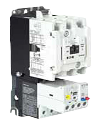
NEMA Starter Shown |
|
AN59KN0A5E
Freedom Series Starter
with C440 Electronic Overload Relay
| NEMA Size |
Continuous Ampere Rating | Service Limit Current Rating (Amps) | Maximum UL Horsepower | |
|---|---|---|---|---|
| 230V | 480V | |||
| 3 | 90 | 104 | — | 50 |
NOTES:
(1) NEMA Size 5 starter available with 60-300A panel mounted CTs. Starter shipped as an assembled unit with 1–5A C440 overload relay (C440A1A005SELAX or C440A2A005SELAX).
Coil Voltage Chart
| Coil Volts and Hertz | Code Suffix | Coil Volts and Hertz | Code Suffix | |
|---|---|---|---|---|
| 120/60 or 110/50 | A | 380-415/50 | L | |
| 240/60 or 220/50 | B | 550/50 | N | |
| 480/60 or 440/50 | C | 24/60, 24/50 | T | |
| 600/60 or 550/50 | D | 24/50 | U | |
| 208/60 | E | 32/50 | V | |
| 277/60 | H | 48/60 | W | |
| 208-240/60 | J | 48/50 | Y | |
| 240/50 | K |
C440 FLA Range
(FVNR and FVR Starters Only)
| NEMA Size |
OLR Code |
FLA Range |
OLR Code |
FLA Rating |
|---|---|---|---|---|
| 00 | 1P6 | 0.33–1.65A | 020 | 4.0–20A |
| 005 | 1.0–5.0A | — | — | |
| 0 | 1P6 | 0.33–1.65A | 020 | 4.0–20A |
| 005 | 1.0–5.0A | — | — | |
| 1 | 1P6 | 0.33–1.65A | 020 | 4.0–20A |
| 005 | 1.0–5.0A | 045 | 9.0–45A | |
| 2 | 005 | 1.0–5.0A | 045 | 9.0–45A |
| 020 | 4.0–20A | — | — | |
| 3 | 100 | 20–100A | — | — |
| 4 | 140 | 28–140A | — | — |
| 5(1) | 300 | 60–300A | — | — |
NOTES:
(1) NEMA Size 5 starter available with 60-300A panel mounted CTs. Starter shipped as an assembled unit with
1–5A C440 overload relay (C440A1A005SELAX or C440A2A005SELAX).
Specifications
| Description | 45mm | 55mm | 110mm |
|---|---|---|---|
| Electrical Ratings | Range | Range | Range |
| Operating voltage (three-phase) and frequency |
690 Vac (60/50 Hz) | 690 Vac (60/50 Hz) | 690 Vac (60/50 Hz) |
| FLA Range | |||
| 0.33–1.65A 1–5A 4–20A 9–45A |
20–100A | 28–140A (NEMA) 35–175A (IEC) |
|
| Use with Contactors | |||
| XT IEC frames | B, C, D | F, G | G, H |
| Freedom NEMA sizes | 00, 0, 1, 2 | 3 | 4 |
| Trip Class | |||
| 10A, 10, 20, 30 Selectable |
10A, 10, 20, 30 Selectable |
10A, 10, 20, 30 Selectable |
|
| Motor Protection | |||
| Thermal overload setting |
1.05 x FLA: does not trip 1.15 x FLA: overload trip |
1.05 x FLA: does not trip 1.15 x FLA: overload trip |
1.05 x FLA: does not trip 1.15 x FLA: overload trip |
| Feature | Range | Range | Range |
| Phase loss | Fixed threshold 50% | Fixed threshold 50% | Fixed threshold 50% |
| Phase unbalance (selectable: enable/disable) |
Fixed threshold 50% | Fixed threshold 50% | Fixed threshold 50% |
| Ground fault (selectable: enable/disable) |
50% of FLA dial setting >150% = 2 sec >250% = 1 sec |
50% of FLA dial setting >150% = 2 sec >250% = 1 sec |
50% of FLA dial setting >150% = 2 sec >250% = 1 sec |
| Reset | Manual/automatic | Manual/automatic | Manual/automatic |
| Indicators | |||
| Trip status | Orange flag | Orange flag | Orange flag |
| Mode LED | One flash: Overload operating properly Two flashes: Current is above FLA dial setting—pending trip |
One flash: Overload operating properly Two flashes: Current is above FLA dial setting—pending trip |
One flash: Overload operating properly Two flashes: Current is above FLA dial setting—pending trip |
| Options | |||
| Remote reset | Yes | Yes | Yes |
| Reset bar | Yes | Yes | Yes |
| Communication expansion module |
Yes | Yes | Yes |
| Communication adapter |
Yes | Yes | Yes |
| Capacity - (Load terminals) | |||
| Terminal capacity | 12–10 AWG (4–6 mm2) 8–6 AWG (6–16 mm2) |
6–1 AWG (16–50 mm2) |
8–4/0 AWG (10–95 mm2) |
| Tightening torque | 20–25 lb-in (2.3–2.8 Nm) 25–30 lb-in (2.8–3.4 Nm) |
25–30 lb-in (2.8–3.4 Nm) |
124 lb-in (14 Nm) |
| Input, auxiliary contact and remote reset terminals Terminal capacity |
2 x (18–12) AWG | 2 x (18–12) AWG | 2 x (18–12) AWG |
| Tightening torque | 7–11 lb-in (0.8–1.2 Nm) |
7–11 lb-in (0.8–1.2 Nm) |
7–11 lb-in (0.8–1.2 Nm) |
| Voltages | |||
| Insulation voltage Ui (three-phase) |
690 Vac | 690 Vac | 690 Vac |
| Insulation voltage Ui (control) |
500 Vac | 500 Vac | 500 Vac |
| Rated impulse withstand voltage |
6000 Vac | 6000 Vac | 6000 Vac |
| Overvoltage category/pollution degree |
III/3 | III/3 | III/3 |
| Auxiliary and Control Circuit Ratings | |||
| Conventional thermal continuous current |
5A | 5A | 5A |
| Rated operational current—IEC AC-15 Make contact (1800 VA) | |||
| 120V | 15A | 15A | 15A |
| 240V | 15A | 15A | 15A |
| 415V | 0.5A | 0.5A | 0.5A |
| 500V | 0.5A | 0.5A | 0.5A |
| Break contact (180 VA) | |||
| 120V | 1.5A | 1.5A | 1.5A |
| 240V | 1.5A | 1.5A | 1.5A |
| 415V | 0.9A | 0.9A | 0.9A |
| 500V | 0.8A | 0.8A | 0.8A |
| IEC DC-13 (L/R F 15 ms1) | |||
| 0–250V | 1.0A | 1.0A | 1.0A |
| Rated operational current—UL
B600 Make contact (3600 VA) |
|||
| 120V | 30A | 30A | 30A |
| 240V | 15A | 15A | 15A |
| 480V | 7.5A | 7.5A | 7.5A |
| 600V | 6A | 6A | 6A |
| Break contact (360 VA) | |||
| 120V | 3A | 3A | 3A |
| 240V | 1.5A | 1.5A | 1.5A |
| 480V | 0.75A | 0.75A | 0.75A |
| 600V | 0.6A | 0.6A | 0.6A |
| R300—Vdc ratings (28 VA) | |||
| 0–120V | 0.22A | 0.22A | 0.22A |
| 250V | 0.11A | 0.11A | 0.11A |
| Short-Circuit Rating without Welding | |||
| Maximum fuse | 6A gG/gL | 6A gG/gL | 6A gG/gL |
| Environmental Ratings | |||
| Ambient temperature (operating) |
–13° to 149°F (–25° to 65°C) |
–13° to 149°F (–25° to 65°C) |
–13° to 149°F (–25° to 65°C) |
| Ambient temperature (storage) |
–40° to 185°F (–40° to 85°C) |
–40° to 185°F (–40° to 85°C) |
–40° to 185°F (–40° to 85°C) |
| Operating humidity UL 991 (H3) |
5% to 95% non-condensing | 5% to 95% non-condensing | 5% to 95% non-condensing |
| Altitude (no derating) NEMA ICS1 |
2000m | 2000m | 2000m |
| Shock (IEC 600068-2-27) |
15g any direction | 15g any direction | 15g any direction |
| Vibration (IEC 60068-2-6) | 3g any direction | 3g any direction | 3g any direction |
| Pollution degree per IEC 60947-4-1 |
3 for product (2 for pcb) |
3 for product (2 for pcb) |
3 for product (2 for pcb) |
| Ingress protection | IP20 | IP20 | IP20 |
| Protection against direct contact when actuated from front (IEC 536) |
Finger- and back-of-hand proof | Finger- and back-of-hand proof | Finger- and back-of-hand proof |
| Mounting position | Any | Any | Any |
| Climatic proofing | Damp heat, constant to IEC 60068-2-30 | Damp heat, constant to IEC 60068-2-30 | Damp heat, constant to IEC 60068-2-30 |
| Electrical/EMC | |||
| Radiated emissions IEC 60947-4-1-Table 15 EN 55011 (CISPIR 11) Group 1, Class A, ISM |
30 mHz to 1000 mHz |
30 mHz to 1000 mHz |
30 mHz to 1000 mHz |
| Conducted emissions IEC 60947-4-1-Table 14 EN 55011 (CISPIR 11) Group 1; Class ISM |
0.15 mHz to 30 mHz |
0.15 mHz to 30 mHz |
0.15 mHz to 30 mHz |
| ESD immunity IEC 60947-4-1 (Table 13) |
±8 kV air, ±6 kV contact | ±8 kV air, ±6 kV contact | ±8 kV air, ±6 kV contact |
| Radiated immunity IEC 60947-4-1 IEC 61000-4-3 |
10 V/m 80 mHz -1000 mHz 3 V/m from 1.4 to 2.7 gHz 80% amplitude modulated 1 kHz sine wave |
10 V/m 80 mHz -1000 mHz 3 V/m from 1.4 to 2.7 gHz 80% amplitude modulated 1 kHz sine wave |
10 V/m 80 mHz -1000 mHz 3 V/m from 1.4 to 2.7 gHz 80% amplitude modulated 1 kHz sine wave |
| Conducted immunity IEC 60947-4-1, IEC 61000-4-6 |
140 dub (10V rms) 150 kHz–100 mHz |
140 dub (10V rms) 150 kHz–100 mHz |
140 dub (10V rms) 150 kHz–100 mHz |
| Fast transient immunity IEC 60947-4-1 (Table 13) IEC 61000-4-4 |
±4 kV using direct method with accessory installed in expansion bay ±2 kV using direct method |
±4 kV using direct method with accessory installed in expansion bay ±2 kV using direct method |
±4 kV using direct method with accessory installed in expansion bay ±2 kV using direct method |
| Surge
immunity IEC 60947-4-1 (Table 13) IEC 61000-4-5 a Class 4 |
Three-phase power inputs: ±4 kV line-to-line (DM) ±4 kV line-to-ground (CM) |
Three-phase power inputs: ±4 kV line-to-line (DM) ±4 kV line-to-ground (CM) |
Three-phase power inputs: ±4 kV line-to-line (DM) ±4 kV line-to-ground (CM) |
| With accessory installed in expansion bay: ±2 kV line-to-line (DM) –>1.2/50 us; 2 kV line-to-earth, 1 kV line-to-line ±4 kV line-to-ground (CM) |
With accessory installed in expansion bay: ±2 kV line-to-line (DM) –>1.2/50 us; 2 kV line-to-earth, 1 kV line-to-line ±4 kV line-to-ground (CM) |
With accessory installed in expansion bay: ±2 kV line-to-line (DM) –>1.2/50 us; 2 kV line-to-earth, 1 kV line-to-line ±4 kV line-to-ground (CM) |
|
| Power freq. magnetic field immunity IEC 60947-4-1, IEC 61000-4-8 |
30 A/m, 50 Hz | 30 A/m, 50 Hz | 30 A/m, 50 Hz |
| Electromagnetic field IEC 60947-4-1 Table 13, IEC 61000-4-3 |
10 V/m | 10 V/m | 10 V/m |
| Distortion IEEE 519 | 5% THD max., 5th harmonic 3% max. | 5% THD max., 5th harmonic 3% max. | 5% THD max., 5th harmonic 3% max. |
| Electrostatic discharge (ESD) IEC 61000-4-2, EN 61131-2 |
4 kV contact 8 kV air discharge |
4 kV contact 8 kV air discharge |
4 kV contact 8 kV air discharge |
| Electrical fast transient (EFT) IEC 61000-4-4, EN 61131-2 |
±2 kV using direct method | ±2 kV using direct method | ±2 kV using direct method |
| Surge immunity IEC 61000-4-5, EN 61131-2 |
±2 kV line-to-ground (CM) | ±2 kV line-to-ground (CM) | ±2 kV line-to-ground (CM) |
| Description | Modbus | DeviceNet | PROFIBUS | Ethernet |
|---|---|---|---|---|
| Electrical/EMC | ||||
| Radiated emissions IEC 60947-4-1—Table 15, EN 55011 (CISPIR 11) Group 1, Class A |
30–1000 mHz | 30–1000 mHz | 30–1000 mHz | 30–1000 mHz |
| Conducted emissions IEC 60947-4-1—Table 14, EN 55011 (CISPIR 11) Group 1, Class A |
0.15–30 mHz | 0.15–30 mHz | 0.15–30 mHz | 0.15–30 mHz |
| ESD immunity IEC 60947-4-1 (Table 13) |
±8 kV air, ±4 kV contact |
±8 kV air, ±4 kV contact |
±8 kV air, ±4 kV contact |
±8 kV air, ±4 kV contact |
| Radiated immunity IEC 60947-4-1 |
10 V/m 80– 1000 mHz 80% amplitude modulated 1 kHz sine wave |
10 V/m 80– 1000 mHz 80% amplitude modulated 1 kHz sine wave |
10 V/m 80– 1000 mHz 80% amplitude modulated 1 kHz sine wave |
10 V/m 80– 1000 mHz 80% amplitude modulated 1 kHz sine wave |
| Conducted immunity IEC 60947-4-1 |
140 dBuV (10V rms) 150 kHz–80 mHz |
140 dBuV (10V rms) 150 kHz–80 mHz |
140 dBuV (10V rms) 150 kHz–80 mHz |
140 dBuV (10V rms) 150 kHz–80 mHz |
| Fast transient immunity IEC 60947-4-1 (Table 13) IEC 6100-4-4 |
±2 kV using direct method | ±2 kV supply and control, ±1 kV communication |
±2 kV supply and control, ±1 kV communication |
±2 kV supply and control, ±1 kV communication |
| Surge immunity IEC 60947-4-1 (Table 13) IEC 61000-4-5 Class 3 |
User IO and communication lines 1: ±1 kV line-to-line (DM) ±2 kV line-to-ground (CM) |
User IO and communication lines: ±0.5 kV line-to-line (DM) ±1 kV line-to-ground (CM) |
User IO and communication lines: ±0.5 kV line-to-line (DM) ±1 kV line-to-ground (CM) |
User IO and communication lines: ±0.5 kV line-to-line (DM) ±1 kV line-to-ground (CM) |
| Electromagnetic field(1) IEC 60947-4-1 (Table 13) IEC 61000-4-3 |
10 V/m | 10 V/m | 10 V/m | 10 V/m |
| Environmental Ratings | ||||
| Ambient temperature (operating) | –4° to 122°F (–20° to 50°C) |
–13° to 122°F (–25° to 50°C) |
–13° to 122°F (–25° to 50°C) |
–13° to 122°F (–25° to 50°C) |
| Ambient temperature (storage) |
–40° to 185°F (–40° to 85°C) |
–40° to 185°F (–40° to 85°C) |
–40° to 185°F (–40° to 85°C) |
–40° to 185°F (–40° to 85°C) |
| Operating humidity | 5–95% noncondensing | 5–95% noncondensing | 5–95% noncondensing | 5–95% noncondensing |
| Altitude (no derating) | 2000m | 2000m | 2000m | 2000m |
| Shock (IEC 600068-2-27) |
15G any direction | 15G any direction | 15G any direction | 15G any direction |
| Vibration (IEC 60068-2-6) |
3G any direction | 3G any direction | 3G any direction | 3G any direction |
| Pollution degree per IEC 60947-1 |
3 | 3 | 3 | 3 |
| Degree of protection | IP20 | IP20 | IP20 | IP20 |
| Overvoltage category per UL 508 |
III | III | III | III |
| DeviceNet | ||||
| DeviceNet connections | — | Group 2, polling, bit strobe, explicit, no UCMM |
— | — |
| DeviceNet baud rate | — | 125K, 250K, 500K | — | — |
| Ethernet | ||||
| Ethernet connections | — | — | — | Integrated two-port switch with dual RJ45 Ethernet connections |
| Ethernet type | — | — | — | Ethernet 10/100 Mbs, AutoMDX, Auto Negotiation |
| PROFIBUS | ||||
| PROFIBUS connections | — | — |
Group 2, polling, bit strobe, explicit, no UCMM |
— |
| PROFIBUS baud rate
|
— | — | 9.6K, 19.2K, 45.45K, 93.75K, 187.5K, 500K, 1.5M, 3M, 6M, 12M |
— |
| C441_ 24 Vdc Input | ||||
| Nominal input voltage | 24 Vdc | 24 Vdc | 24 Vdc | 24 Vdc |
| Operating voltage | 18–30 Vdc | 18–30 Vdc | 18–30 Vdc | 18–30 Vdc |
| Number of inputs | 4 | 4 | 4 | 4 |
| Signal delay | 5 ms (programmable to 65 sec) | 5 ms (programmable to 65 sec) | 5 ms (programmable to 65 sec) | 5 ms (programmable to 65 sec) |
| OFF-state voltage | <6 Vdc | <6 Vdc | <6 Vdc | <6 Vdc |
| ON-state voltage | >18 Vdc | >18 Vdc | >10 Vdc | >18 Vdc |
| Nominal input current | 5 mA | 5 mA | 5 mA | 5 mA |
| Isolation | 1500V | 1500V | 1500V | 1500V |
| Terminal screw torque | 7–9 in-lb | 7–9 in-lb | 7–9 in-lb | 7–9 in-lb |
| 24V source current | 50 mA | 50 mA | 50 mA | 50 mA |
| Operating Voltage Range—DC Input Modules | ||||
| OFF state | 0–6 Vdc | 0–6 Vdc | 0–6 Vdc | 0–6 Vdc |
| Transition region | 6–18 Vdc | 6–18 Vdc | 6–18 Vdc | 6–18 Vdc |
| ON state | 18–30 Vdc | 18–30 Vdc | 18–30 Vdc | 18–30 Vdc |
| C441_ 120 Vac Input | ||||
| Nominal input voltage | 120 Vac | 120 Vac | 120 Vac | 120 Vac |
| Operating voltage | 80–140 Vac | 80–140 Vac | 80–140 Vac | 80–140 Vac |
| Number of inputs | 4 | 4 | 4 | 4 |
| OFF-state voltage | <30 Vac | <30 Vac | <20 Vac | <30 Vac |
| ON-state voltage | >80 Vac | >80 Vac | >70 Vac | >80 Vac |
| Nominal input current | 15 mA | 15 mA | 15 mA | 15 mA |
| Signal delay | 1/2 cycle | 1/2 cycle | 1/2 cycle | 1/2 cycle |
| Isolation | 1500V | 1500V | 1500V | 1500V |
| Terminal screw torque | 7–9 in-lb | 7–9 in-lb | 7–9 in-lb | 7–9 in-lb |
| Operating Voltage Range—AC Input Modules | ||||
| OFF state | 0–30 Vac | 0–30 Vac | 0–30 Vac | 0–30 Vac |
| Transition region | 30–80 Vac | 30–80 Vac | 30–80 Vac | 30–80 Vac |
| ON state | 80–140 Vac | 80–140 Vac | 80–140 Vac | 80–140 Vac |
| Output Modules | ||||
| Nominal voltage | 120 Vac 24 Vdc |
120 Vac 24 Vdc |
120 Vac 24 Vdc |
120 Vac 24 Vdc |
| Number of outputs | (2) 1NO Form A 1NO/NC Form C |
(2) 1NO Form A 1NO/NC Form C |
(2) 1NO Form A 1NO/NC Form C |
(2) 1NO Form A 1NO/NC Form C |
| Relay OFF time | 3 ms | 3 ms | 3 ms | 3 ms |
| Relay ON time | 7 ms | 7 ms | 7 ms | 7 ms |
| Max. current per point(1) | 5A (B300 rated) | 5A (B300 rated) | 5A (B300 rated) | 5A (B300 rated) |
| Electrical life | 100,000 cycles | 100,000 cycles | 100,000 cycles | 100,000 cycles |
| Mechanical life | 1,000,000 cycles | 1,000,000 cycles | 1,000,000 cycles | 1,000,000 cycles |
NOTES:
(1) Relates to C441M Only.
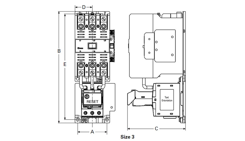
Dimensions
Non-Reversing
Non-Reversing
| NEMA Size |
A | B | C | D | E |
|---|---|---|---|---|---|
| 00, 0 | 1.97 (50.0) | 6.60 (167.6) | 4.90 (124.5) | — | 6.18 (157.0) |
| 1, 2 | 2.60 (65.0) | 7.10 (180.0) | 4.98 (126.5) | 2.00 (50.8) | 6.50 (165.0) |
| 3 | 4.09 (103.8) | 11.40 (289.6) | 5.92 (150.3) | 1.77 (44.9) | 10.81 (274.6) |
| 4 | 7.10 (179.0) | 17.00 (432.0) | 7.00 (177.0) | 3.70 (94.0) | 16.30 (415.0) |
| 5 | 7.00 (177.8) | 17.81 (452.3) | 8.08 (205.2) | 6.00 (152.4) | 16.01 (406.6) |
NOTES:
(1) Includes cross wiring overhang.
(2) See catalog listings for type and location of auxiliary contacts supplied with a particular starter.
Reversing
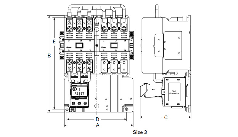
Reversing
| NEMA Size |
A | B | C | D | E |
|---|---|---|---|---|---|
| 00, 0 | 5.20 (132.0) | 7.40 (187.0) | 4.90 (125.0) | 3.50 (89.0) | 6.90 (174.0) |
| 1 | 6.70 (171.0) | 7.10 (180.0) | 4.98 (126.5) | 5.25 (133.0) | 5.70 (144.0) |
| 2 | 6.70 (171.0) | 8.10 (205.0) | 4.98 (126.5) | 5.25 (133.0) | 6.70 (170.0) |
| 3 | 8.08 (205.2) | 11.35 (288.3) | 6.00 (152.0) | 7.00 (177.8) | 10.77 (273.6) |
| 4 | 14.60 (371.0) | 17.10 (433.0) | 7.00 (177.0) | 13.50 (343.0) | 16.30 (145.0) |
| 5 | 14.50 (368.3) | 17.81 (452.3) | 8.06 (204.8) | 13.50 (342.9) | 16.00 (406.6) |
NOTES:
(1) Includes cross wiring overhang.
(2) See catalog listings for type and location of auxiliary contacts supplied with a particular starter.