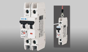
Type "C" Characteristics - Designed for Inductive Loads
Suitable for applications where medium levels of inrush current are expected. Instantaneous trip is 5 to 10 x rating of device (/n).
Applications include small transformers, lighting, pilot devices, control circuits, and coils. Medium magnet trip point.
Eaton Klockner Moeller
MINI BREAKERS & SUPP. PROTECTORS
UL 489 DIN Rail Branch Circuit Breakers / Type-C & Type-D
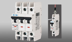
Type "D" Characteristics - Designed for Highly Inductive Loads
Suitable for applications where high levels of inrush current are expected. Instantaneous trip is 10 to 20 x rating of device (/n).
The high magnetic point prevents nuisance tripping in high inductive applications such as motors, transformers, and power supplies.
Type "C" Characteristics - Designed for Inductive Loads
Suitable for applications where medium levels of inrush current are expected. Instantaneous trip is 5 to 10 x rating of device (/n).
Applications include small transformers, lighting, pilot devices, control circuits, and coils. Medium magnet trip point.
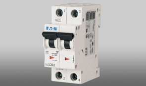
Type "D" Characteristics - Designed for Highly Inductive Loads
Suitable for applications where high levels of inrush current are expected. Instantaneous trip is 10 to 20 x rating of device (/n).
The high magnetic point prevents nuisance tripping in high inductive applications such as motors, transformers, and power supplies.
UL 1077 DIN Rail Supplementary Protectors - Type B
Type "B" Characteristics - Designed for Resistive or Slightly Inductive Loads
Suitable for applications where protection against low level short circuit faults in control wiring is desired.
Instantaneous trip is 3 to 5 x continuous rating of device (/n).
Applications include PLC wiring, business equipment, lighting, appliances and some motors. Low magnetic trip point.
UL 1077 DIN Rail Supplementary Protectors - Type C
Type "C" Characteristics - Designed for Inductive Loads
Suitable for applications where medium levels of inrush current are expected. Instantaneous trip is 5 to 10 x rating of device (/n).
Applications include small transformers, lighting, pilot devices, control circuits, and coils. Medium magnetic trip point.
UL 1077 DIN Rail Supplementary Protectors - Type D
Type "D" Characteristics - Designed for Highly Inductive Loads
Suitable for applications where high levels of inrush current are expected. Instantaneous trip is 10 to 20 x rating of device (/n).
The high magnetic trip point prevents nuisance tripping in high inductive applications such as motors, transformers, and power supplies.
Type "D" Characteristics - Designed for Highly Inductive loads
Suitable for applications where high levels of inrush current are expected. Instantaneous trip is 10 to 20 x rating of device (/n).
The high magnetic trip point prevents nuisance tripping in high inductive applications such as motors, transformers, and power supplies.
UL 1077 DIN Rail Supplementary Protectors - Type K
Type "K" Characteristics - Designed for Motors, Transformers, and Upstream Electronics.
Suitable for applications where medium levels of inrush current are expected. Instantaneous trip is 8 to 12 x continuous rating of device (/n).
The high magnetic trip point is ideal for motors and transformers.
The narrow range (compared with the type D curve) makes it ideal for applications where nuisance tripping is not an issue.
| Rated Current (Amps) | 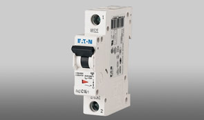 |
 |
 |
|||
| 1 Pole | 2 Pole | 3 Pole | ||||
| Moeller | Eaton | Moeller | Eaton | Moeller | Eaton | |
| 0.5 | FAZ-K0,5/1 | — | FAZ-K0,5/2 | — | FAZ-K0,5/3 | — |
| 1 | FAZ-K1/1 | — | FAZ-K1/2 | — | FAZ-K1/3 | — |
| 1.6 | FAZ-K1,6/1 | — | FAZ-K1,6/2 | — | FAZ-K1,6/3 | — |
| 2 | FAZ-K2/1 | — | FAZ-K2/2 | — | FAZ-K2/3 | — |
| 3 | FAZ-K3/1 | — | FAZ-K3/2 | — | FAZ-K3/3 | — |
| 4 | FAZ-K4/1 | — | FAZ-K4/2 | — | FAZ-K4/3 | — |
| 6 | FAZ-K6/1 | — | FAZ-K6/2 | — | FAZ-K6/3 | — |
| 8 | FAZ-K8/1 | — | FAZ-K8/2 | — | FAZ-K8/3 | — |
| 10 | FAZ-K10/1 | — | FAZ-K10/2 | — | FAZ-K10/3 | — |
| 13 | FAZ-K13/1 | — | FAZ-K13/2 | — | FAZ-K13/3 | — |
| 16 | FAZ-K16/1 | — | FAZ-K16/2 | — | FAZ-K16/3 | — |
| 20 | FAZ-K20/1 | — | FAZ-K20/2 | — | FAZ-K20/3 | — |
| 25 | FAZ-K25/1 | — | FAZ-K25/2 | — | FAZ-K25/3 | — |
| 32 | FAZ-K32/1 | — | FAZ-K32/2 | — | FAZ-K32/3 | — |
| 40 | FAZ-K40/1 | — | FAZ-K40/2 | — | FAZ-K40/3 | — |
| 50 | FAZ-K50/1 | — | FAZ-K50/2 | — | FAZ-K50/3 | — |
| 63 | FAZ-K63/1 | — | FAZ-K63/2 | — | FAZ-K63/3 | — |
Type "K" Characteristics - Designed for Highly Inductive loads
Suitable for applications where high levels of inrush current are expected. Instantaneous trip is 10 to 20 x rating of device (/n).
The high magnetic trip point prevents nuisance tripping in high inductive applications such as motors, transformers, and power supplies.
| Rated Current (Amps) |  |
 |
 |
|||
| 4 Poles | 1 Pole + Neutral | 3 Poles + Neutral | ||||
| Moeller | Eaton | Moeller | Eaton | Moeller | Eaton | |
| 0.5 | FAZ-K0.5/4 | — | FAZ-K0.5/1N | — | FAZ-K0.5/3N | — |
| 1 | FAZ-K1/4 | — | FAZ-K1/1N | — | FAZ-K1/3N | — |
| 1.6 | FAZ-K1.6/4 | — | FAZ-K1.6/1N | — | FAZ-K1.6/3N | — |
| 2 | FAZ-K2/4 | — | FAZ-K2/1N | — | FAZ-K2/3N | — |
| 3 | FAZ-K3/4 | — | FAZ-K3/1N | — | FAZ-K3/3N | — |
| 4 | FAZ-K4/4 | — | FAZ-K4/1N | — | FAZ-K4/3N | — |
| 6 | FAZ-K6/4 | — | FAZ-K6/1N | — | FAZ-K6/3N | — |
| 8 | FAZ-K8/4 | — | FAZ-K8/1N | — | FAZ-K8/3N | — |
| 10 | FAZ-K10/4 | — | FAZ-K10/1N | — | FAZ-K10/3N | — |
| 13 | FAZ-K13/4 | — | FAZ-K13/1N | — | FAZ-K13/3N | — |
| 16 | FAZ-K16/4 | — | FAZ-K16/1N | — | FAZ-K16/3N | — |
| 20 | FAZ-K20/4 | — | FAZ-K20/1N | — | FAZ-K20/3N | — |
| 25 | FAZ-K25/4 | — | FAZ-K25/1N | — | FAZ-K25/3N | — |
| 32 | FAZ-K32/4 | — | FAZ-K32/1N | — | FAZ-K32/3N | — |
| 40 | FAZ-K40/4 | — | FAZ-K40/1N | — | FAZ-K40/3N | — |
| 50 | FAZ-K50/4 | — | FAZ-K50/1N | — | FAZ-K50/3N | — |
| 63 | FAZ-K63/4 | — | FAZ-K63/1N | — | FAZ-K63/3N | — |
UL 1077 DIN Rail Supplementary Protectors - Type Z and Type S
Type "Z" Characteristics - Designed for Protection of Electronic Devices.
Suitable for applications where semiconductors and other components that fail open are used.
Instantaneous trip is 2 to 3 x continuous rating of device (/n).
The short thermal delay and low magnetic trip point are ideal for applications where devices and components
have low surge and short circuit tolerances.
| Rated Current (Amps) | |
|
|
|
||||
| 1 Pole | 2 Pole | 3 Pole | 4 Pole | |||||
| Moeller | Eaton | Moeller | Eaton | Moeller | Eaton | Moeller | Eaton | |
| 0.5 | FAZ-Z0,5/1 | — | FAZ-Z0,5/2 | — | FAZ-Z0,5/3 | — | FAZ-Z0,5/4 | — |
| 1 | FAZ-Z1/1 | — | FAZ-Z1/2 | — | FAZ-Z1/3 | — | FAZ-Z1/4 | — |
| 1.6 | FAZ-Z1,6/1 | — | FAZ-Z1,6/2 | — | FAZ-Z1,6/3 | — | FAZ-Z1,6/4 | — |
| 2 | FAZ-Z2/1 | — | FAZ-Z2/2 | — | FAZ-Z2/3 | — | FAZ-Z2/4 | — |
| 3 | FAZ-Z3/1 | — | FAZ-Z3/2 | — | FAZ-Z3/3 | — | FAZ-Z3/4 | — |
| 4 | FAZ-Z4/1 | — | FAZ-Z4/2 | — | FAZ-Z4/3 | — | FAZ-Z4/4 | — |
| 6 | FAZ-Z6/1 | — | FAZ-Z6/2 | — | FAZ-Z6/3 | — | FAZ-Z6/4 | — |
| 8 | FAZ-Z8/1 | — | FAZ-Z8/2 | — | FAZ-Z8/3 | — | FAZ-Z8/4 | — |
| 10 | FAZ-Z10/1 | — | FAZ-Z10/2 | — | FAZ-Z10/3 | — | FAZ-Z10/4 | — |
| 13 | FAZ-Z13/1 | — | FAZ-Z13/2 | — | FAZ-Z13/3 | — | FAZ-Z13/4 | — |
| 16 | FAZ-Z16/1 | — | FAZ-Z16/2 | — | FAZ-Z16/3 | — | FAZ-Z16/4 | — |
| 20 | FAZ-Z20/1 | — | FAZ-Z20/2 | — | FAZ-Z20/3 | — | FAZ-Z20/4 | — |
| 25 | FAZ-Z25/1 | — | FAZ-Z25/2 | — | FAZ-Z25/3 | — | FAZ-Z25/4 | — |
| 32 | FAZ-Z32/1 | — | FAZ-Z32/2 | — | FAZ-Z32/3 | — | FAZ-Z32/4 | — |
| 40 | FAZ-Z40/1 | — | FAZ-Z40/2 | — | FAZ-Z40/3 | — | FAZ-Z40/4 | — |
| 50 | FAZ-Z50/1 | — | FAZ-Z50/2 | — | FAZ-Z50/3 | — | FAZ-Z50/4 | — |
| 63 | FAZ-Z63/1 | — | FAZ-Z63/2 | — | FAZ-Z63/3 | — | FAZ-Z63/4 | — |
Type "S" Characteristics - Designed for Control Circuits with High Inrush.
Suitable for applications with highly inductive loads, especially in control circuits with coils and light filaments.
Instantaneous response between 13 to 17 x rating of device (/n).
| Rated Current (Amps) | |
|
||
| 1 Pole | 2 Pole | |||
| Moeller | Eaton | Moeller | Eaton | |
| 1 | FAZ-S1/1 | — | FAZ-S1/2 | — |
| 2 | FAZ-S2/1 | — | FAZ-S2/2 | — |
| 3 | FAZ-S3/1 | — | FAZ-S3/2 | — |
| 4 | FAZ-S4/1 | — | FAZ-S4/2 | — |
| 6 | FAZ-S6/1 | — | FAZ-S6/2 | — |
| 10 | FAZ-S10/1 | — | FAZ-S10/2 | — |
| 16 | FAZ-S16/1 | — | FAZ-S16/2 | — |
| 20 | FAZ-S20/1 | — | FAZ-S20/2 | — |
| 25 | FAZ-S25/1 | — | FAZ-S25/2 | — |
| 32 | FAZ-S32/1 | — | FAZ-S32/2 | — |
| 40 | FAZ-S40/1 | — | FAZ-S40/2 | — |