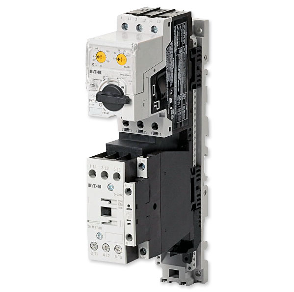
Eaton/Moeller |

MSC-DE-12-M17(230V50HZ) shown |
MSC-DE-32-M25(24VDC) Motor Starter |
||||
| Motor data Rated short-circuit current |
Setting Range Overload Release Ir  |
Old Moeller Part Number |
New Eaton Part Number |
|
|---|---|---|---|---|
| 380 – 415 V Coordination type “1” lq kA |
380 – 415 V Coordination type “2” lq kA |
|||
| 100 | — | 8.0 - 32.0A | MSC-DE-32-M25(24VDC) | XTSE032B025CTDNL |
MSC-DE-32-M25(24VDC) Technical Data |
| Delivery programme | |
|---|---|
| Basic function | DOL starters (complete devices) |
| Basic device | MSC |
 |
|
| Notes | Also suitable for motors with efficiency class IE3. IE3-ready devices are identified by the logo on their packaging. |
| Motor rating | |||
|---|---|---|---|
| Motor Rating — AC-3 | |||
| 380 V 400 V 415 V | P | kW | 11 |
| 500 V | P | kW | 15 |
| Rated operational current — AC-3 | |||
| 400 V | Ie | A | 21.7 |
| 500 V | Ie | A | 23.4 |
| Rated short-circuit current 380 - 400 V | Iq | kA | 100 |
| Rated short-circuit current 500 V | Iq | kA | 50 |
| Setting range | |||
Setting range of overload releases  |
Ir | A | 8 - 32 |
Short-circuit releases  |
|||
Non-delayed  |
Irm | A | 448 |
| Coordination | Type of coordination "1" Type of coordination "2" |
||
| Contact sequence |  |
||
| Actuating voltage | 24 V DC | ||
| Motor-protective circuit-breakers PKE32/XTU-32 |
| Contactor DILM25-10(...) |
| DOL starter wiring set Mechanical connection element and electrical electric contact module PKZM0-XDM32 |
Notes The DOL starter (complete devices) consists of a PKE motor-protective circuit-breaker and a DILM contactor. With the adapter-less top-hat rail mounting of starters up to 15A, only the motor-protective circuit-breaker on the top-hat rail requires an adapter. The contactors are provided with mechanical support via a mechanical connection element. Control wire guide with max. 6 conductors up to 2.5°mm external diameter or 4 conductors up to 3.5°mm external diameter. From 16 A, the motor-protective circuit-breaker and contactor are mounted on the top-hat rail adapter plate. The connection of the main circuit between PKE and contactor is established with electrical contact modules. When using DILA-XHIT... auxiliary contacts with MSC-DE-... DOL starters, the plug-in electrical connectors can be removed without removing the front-mounted auxiliary contact. Cannot be combined with NHI-E...PKZ0-C. MSC-DEA... DOL starters are prepared for communications via SmartWire-DT. In order to be used this way, they first need to be expanded with the PKE-SWD-32 communications module. |
| Motor output/rated motor current | |||||||
|---|---|---|---|---|---|---|---|
| Motor Rating P kW |
Rated Motor Current AC-3 |
||||||
| 220 V 230 V 240 V Iq=100kA I A |
380 V 400 V Iq=100kA I A |
415 V Iq=65kA I A |
440 V Iq=65kA I A |
500 V Iq=50kA I A |
500 V with CL-PKZ0 Iq=100kA I A |
660 V 690 V Iq=50kA I A |
|
| 2.2 | 8.7 | - | - | - | - | - | - |
| 3 | 11.5 | - | - | - | - | - | - |
| 4 | 14.8 | 8.5 | 8.5 | - | - | - | - |
| 5.5 | 19.6 | 11.3 | 11.3 | 10.2 | 9 | 9 | - |
| 7.5 | - | 15.2 | 15.2 | 13.8 | 12.1 | 12.1 | 8.8 |
| 11 | - | 21.7 | 21.7 | 19.7 | 17.4 | 17.4 | 12.6 |
| 15 | - | - | - | - | 23.4 | 23.4 | 17 |
| Technical data | |||
|---|---|---|---|
| General | |||
| Standards | IEC/EN 60947-4-1, VDE 0660 | ||
| Main conducting paths | |||
| Rated impulse withstand voltage | Uimp | V AC | 6000 |
| Overvoltage category/pollution degree | III/3 | ||
| Rated operational voltage | Ue | V | 230 - 415 |
| Rated operational current | |||
| Open, 3-pole: 50-60 Hz 380 V 400 V |
Ie | A | 25 |
| Additional technical data | |||
| Motor protective circuit breaker PKZM0, PKE |
PKZM0 motor-protective circuit-breakers, see motor-protective circuit-breakers/PKZM0 product group DILM contactors, see contactors product group DILET timing relay, ETR, see contactors, electronic timing relays product group |
||
| DC Operated | Sealing | W | 0.5 |
| Data for design verification according to IEC/EN 61439 | |||
| Technical data for design verification | |||
| Heat dissipation capacity | Pdiss | W | 0 |
| IEC/EN 61439 design verification | — | ||
| 10.2 Strength of materials and parts | — | ||
| 10.2.2 Corrosion resistance | Meets the product standard's requirements. | ||
| 10.2.3.1 Verification of thermal stability of enclosures |
Meets the product standard's requirements. | ||
| 10.2.3.2 Verification of resistance of insulating materials to normal heat |
Meets the product standard's requirements. | ||
| 10.2.3.3 Verification of resistance of insulating materials to abnormal heat and fire due to internal electric effects |
Meets the product standard's requirements. | ||
| 10.2.4 Resistance to ultra-violet (UV) radiation |
Meets the product standard's requirements. | ||
| 10.2.5 Lifting | Does not apply, since the entire switchgear needs to be evaluated. |
||
| 10.2.6 Mechanical impact | Does not apply, since the entire switchgear needs to be evaluated. |
||
| 10.2.7 Inscriptions | Meets the product standard's requirements. | ||
| 10.3 Degree of protection of ASSEMBLIES | Does not apply, since the entire switchgear needs to be evaluated. |
||
| 10.4 Clearances and creepage distances | Meets the product standard's requirements. | ||
| 10.5 Protection against electric shock | Does not apply, since the entire switchgear needs to be evaluated. |
||
| 10.6 Incorporation of switching devices and components |
Does not apply, since the entire switchgear needs to be evaluated. |
||
| 10.7 Internal electrical circuits and connections | Is the panel builder's responsibility. | ||
| 10.8 Connections for external conductors | Is the panel builder's responsibility. | ||
| 10.9 Insulation properties | — | ||
| 10.9.2 Power-frequency electric strength | Is the panel builder's responsibility. | ||
| 10.9.3 Impulse withstand voltage | Is the panel builder's responsibility. | ||
| 10.9.4 Testing of enclosures made of insulating material |
Is the panel builder's responsibility. | ||
| 10.10 Temperature rise | The panel builder is responsible for the temperature rise calculation. Eaton will provide heat dissipation data for the devices. |
||
| 10.11 Short-circuit rating | Is the panel builder's responsibility. The specifications for the switchgear must be observed. |
||
| 10.12 Electromagnetic compatibility | Is the panel builder's responsibility. The specifications for the switchgear must be observed. |
||
| 10.13 Mechanical function | The device meets the requirements, provided the information in the instruction leaflet (IL) is observed. |
||
| Technical data ETIM 5.0 | |||
| Low-voltage industrial components (EG000017) / Motor starter combination (EC001037) | |||
| Electric engineering, automation, process control engineering / Low-voltage switch technology / Load breakout, motor breakout / Motor starter combination (ecl@ss8-27-37-09-05 [AJZ718009]) |
|||
| Function | — | Direct starter | |
| Rated control supply voltage Us at AC 50HZ | V | 0 - 0 | |
| Rated control supply voltage Us at AC 60HZ | V | 0 - 0 | |
| Rated control supply voltage Us at DC | V | 24 - 24 | |
| Voltage type for actuating | — | DC | |
| Rated operation power at AC-3, 400 V | kW | 12.5 | |
| Rated operation current Ie | A | 21.7 | |
| Conditioned rated short-circuit current Iq | kA | 100 | |
| Setting range overload protector | A | 8 - 32 | |
| With short-circuit release | — | Yes | |
| Type of coordination | — | 2 | |
| Connection type main current circuit | — | Screw connection | |
| Degree of protection (IP) | — | IP20 | |
| Suited for bus connection | — | Yes | |
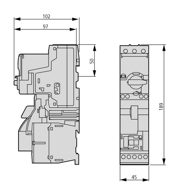
MSC-DE-32-M25(24VDC) Dimensions |
||
 |
||
