Eaton/Moeller |
Continuing Moeller's Motor-Protective Circuit Breaker Tradition |
|
With its PKE series of devices, Eaton continues to improve and enhance Moeller's motor-protective circuit breakers. Moeller had already developed the motor-protective circuit-breaker PKZ in 1932. Our ideas and developments in the development center in Bonn have decisively influenced the trends in the protection of motors since then. The results are progressive concepts and marketable product innovations that again and again assume the role of international trendsetting, pioneering products. |
It was Moeller who pioneered the integration of overload protection and short-circuit protection into a compact device thus abolishing the usual separation between both protective functions as used up to then. The awareness of this long tradition in the motor protection field has helped establish and maintain a core competence, which has been continued through to today by Eaton. The term PKZ is not just the embodiment of quality, but also the generally used synonym by experts for motor-protective circuit-breakers. |
 |
|
Motor-Protective Circuit-Breaker PKE
Switch and Protect Motors up to 65 A with
Electronic Wide-Range Overload Protection
Modular design. Highest level of flexibility. |
|
The functional safety and the service life of a motor depends mainly on the motor protection. Motor-protective circuit-breakers PKE with electronic wide-range overload protection offer an interesting alternative to the bimetal solutions here and complement the intelligent PKZ series from Eaton. |
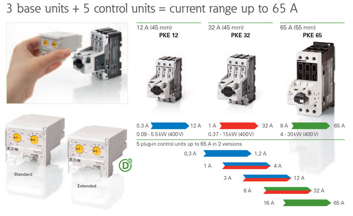
They provide the highest level of flexibility featuring a compact and modular design with its plug-in control unit. Control units are also available for system protection applications. The PKE can be re-equipped in a single step for motor and system protection with various plug-in control units. |
 |
|
Device Overview
 |
|||
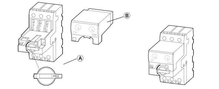
| A PKE... motor-protective circuit-breaker B PKE-XTU(W)(A)-… trip block |
Complete device, motor-protective circuit-breaker PKE…/XTU(W)(A)-… |
||
PKE Description
| Overload protection with motor-protective circuitbreakers | |
|---|---|
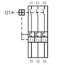 |
The PKE device is a three-pole motor-protective circuitbreaker with electronic wide-range overload protection designed to monitor electric motors for overload. In the event of an overload trip, the PKE isolates all poles of the main circuit through trip block PKE-XTU(W)(A)-… to immediately stop the flow of current to the monitored motor. Circuit diagram for motor-protective circuit-breaker PKE with trip block PKE-XTU(W)(A)-… |
| Setting range of the motor-protective circuit-breaker | |
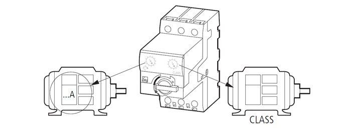
| The rated motor current of the PKE is set with the setting dial |
|
 |
|
| With two basic devices (PKE12 for up to 12 A, PKE32 for up to 32 A and PKE65 up to 65 A), and six different electronic trip blocks, the PKE can monitor motors with a rated current from 0.3 to 65 A. The tripping blocks and rated operational current must be set on all trip blocks PKE-XTU(W)(A)-… With trip blocks PKE-XTU(W)A-… operational data, such as currents and trip causes can also be transmitted to a higherlevel fieldbus system through SmartWire-DT. This does not affect motor protection. |
|
| Part Number | Setting Range Ie [A] |
|---|---|
| PKE12/XTU(A)-1.2 | 0.3 - 1.2 |
| PKE12/XTU(A)-4 PKE32/XTU(A)-4 |
1 - 4 |
| PKE12/XTU(A)-12 PKE32/XTU(A)-12 |
3 - 12 |
| PKE32/XTU(A)-32 | 8 - 32 |
| PKE65/XTUW(A)-32 | 8 - 32 |
| PKE65/XTU(A)-65 | 16 - 65 |
| Setting the tripping CLASS | |
|---|---|
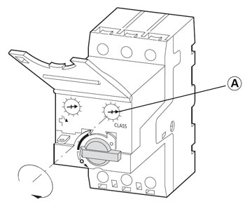 A Tripping class setting dial |
Motor-protective circuit-breaker PKE is suitable for both normal starting and heavy starting duty. The tripping behavior of the overload trip is defined by the set tripping class.
For normal and overload operation, switchgear is designed for CLASS 10. To prevent overloading switchgear and cables during heavy starting duty, rated operational current IeCLASS of switchgear and cables must be overdimensioned according to the tripping class set on the motor-protective circuit-breaker PKE. |
| Test Function | |
|---|---|
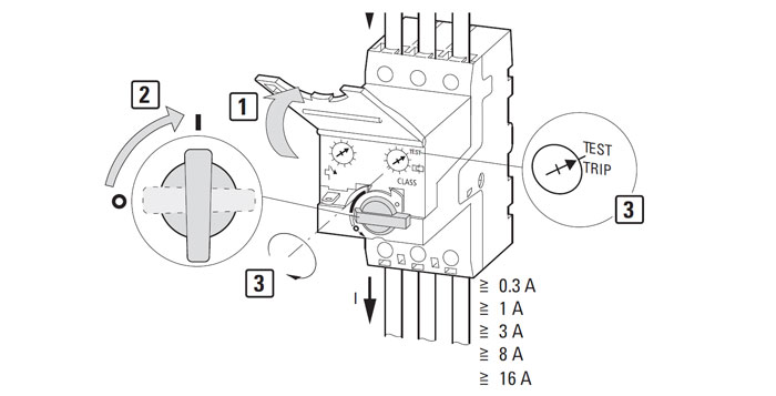 Setting the test function |
|
When you actuate the test device of the powered-up motor protective circuit-breaker PKE with a screwdriver  , the motor-protective circuit-breaker trips. To allow the active motor-protective circuit-breaker PKE to trip in its test position, a current corresponding at least with the minimum set value at the trip block must flow. , the motor-protective circuit-breaker trips. To allow the active motor-protective circuit-breaker PKE to trip in its test position, a current corresponding at least with the minimum set value at the trip block must flow.When the test function is operated with the motor-protective circuit-breaker switched on, the PKE trips and all main contacts open. The lines downstream of the PKE can then be tested for zero voltage. To allow the powered-on motorprotective circuit-breaker PKE to trip in its test position, a current corresponding at least with the minimum set value of the trip block must flow. To maintain a proper working state, repeated testing of electrical plants and equipment is necessary. |
|
| Using the device | |
|---|---|
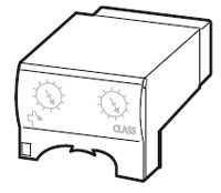 |
Before commissioning the motor-protective circuit-breaker, the rated motor current must be set with the setting dial on the PKE The setting dial on the trip block has 16 discrete positions for the following settings: |
| 0.3 - 1.2 A | 0.30 | 0.33 | 0.36 | 0.40 | 0.43 | 0.47 | 0.50 | 0.56 |
| 0.63 | 0.70 | 0.77 | 0.83 | 0.90 | 1.00 | 1.10 | 1.20 | |
| 1 - 4 A | 1.00 | 1.10 | 1.20 | 1.30 | 1.42 | 1.55 | 1.70 | 1.90 |
| 2.10 | 2.40 | 2.60 | 2.80 | 3.00 | 3.30 | 3.70 | 4.00 | |
| 3 - 12 A | 3.00 | 3.30 | 3.60 | 4.00 | 4.30 | 4.70 | 5.00 | 5.60 |
| 6.30 | 7.00 | 7.70 | 8.30 | 9.00 | 10.00 | 11.00 | 12.00 | |
| 8 - 32 A | 8.00 | 8.80 | 9.70 | 10.50 | 11.50 | 12.50 | 13.50 | 15.00 |
| 17.00 | 19.00 | 20.50 | 22.00 | 24.00 | 27.00 | 29.00 | 32.00 | |
| 16 - 65 A | 16.00 | 17.50 | 19.50 | 21.00 | 23.00 | 25.00 | 27.00 | 30.00 |
| 34.00 | 38.00 | 41.00 | 44.00 | 48.00 | 53.00 | 58.00 | 65.00 |
| Fitting the device | |
|---|---|
| Approved mounting position for PKE motor-protective circuit-breakers 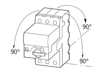 |
Main circuit wiring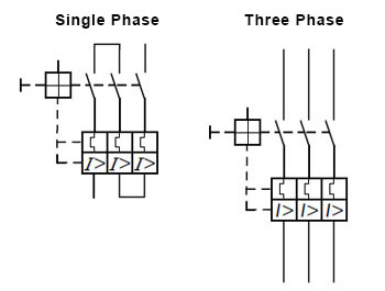 |
