| Home | ||
| ||
| ||
| ||
| ||
| ||
| ||
| ||
| ||
| ||
| ||
| ||
| ||
| Reduced Voltage Soft Starters | ||
| ||
| ||
| ||
| ||
| Moeller PDF Archive |
Eaton/Moeller |
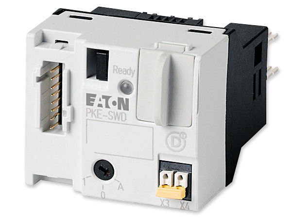
PKE-SWD-32 shown |

SmartWire-DT communication circuit |
|
| Discription | Moeller / Eaton Part Number |
|---|---|
| SmartWire-DT for PKE12/32, manual/auto |
PKE-SWD-32 |
PKE-SWD-32 Technical Data |
|
| Delivery program | |
|---|---|
| Product range | SmartWire-DT slave |
| Subrange | SmartWire-DT PKE module for motor-starter combinations |
| Basic function | Motor protection Motor protection for heavy starting duty |
| Product range | Accessories |
| Accessories | SmartWire-DT PKE module (motor-starter combinations) |
| Function | For connecting PKE motor-starter combination MSC-DEA... with PKE-XTUA-... trip blocks with a rated motor output of 15 kW/400 V to SmartWire-DT |
| Description | Mounting on DILM contactor with 24 V DC control voltage. One module per contactor and PKE necessary Additional SWD contactor module required fir actuation of reversing starter. 1 electrical interlock for the surface mounting of reversing starters. 1-0-A switch for manual or automatic operation. Selectable overload relay function (ZMR) for switching off the contactor on overload. Wiring sets DILM 12-XRL and PKZM0-XRM12 cannot be used. For current consumption of the contactor coils > 3 A (UL/CSA > 2 A) use additional power feeder module. A2 connections must not be bridged. |
| Messages | Switch position contactor/PKE/1-0-A switch Motor current in % Thermal motor image in % Trip indications (Overload, Short-circuit,...) Set value of overload releases Set time lag (CLASS) Part no. of trip block |
| Commands | Contactor actuation Activation Overload relay function (ZMR) |
| Information about equipment supplied | Connecting cable between module and trip block PKE-XTUA-... included as standard. |
| For use with | DILM(C)7... - DILM(C)32 MSC-DEA |
| Connection to SmartWire-DT | yes |
| Connection type | Push in terminals |
| Technical data | |
| General | |
| Standards | IEC/EN 61131-2 EN 50178 IEC/EN 60947 |
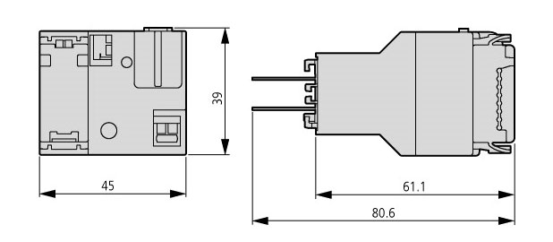
| Dimensions (W x H x D) | 45 x 38 x 76 mm |
| Weight | 0.04 kg |
| Mounting | on DILM7... DILM32 |
| Mounting position | as DILM7 to DILM32 |
| Ambient conditions, mechanical | |
| Protection type (IEC/EN 60529, EN50178, VBG 4) |
IP20 |
| Vibrations (IEC/EN 61131-2:2008) | |
| Constant amplitude 3,5 mm | 5 - 8.4 Hz |
| Constant acceleration 1 g | 8.4 - 150 Hz |
| Mechanical shock resistance (IEC/EN 60068-2-27) semi-sinusoidal 15 g/11 ms |
9 Impacts |
| Drop to IEC/EN 60068-2-31 (Drop height) | 50 mm |
| Free fall, packaged (IEC/EN 60068-2-32) | 0.3 m |
| Electromagnetic compatibility (EMC) | |
| Overvoltage category | II |
| Pollution degree | 2 |
| Electrostatic discharge (IEC/EN 61131-2:2008) |
|
| Air discharge (Level 3) | 8 kV |
| Contact discharge (Level 2) | 4 kV |
| Electromagnetic fields (IEC/EN 61131-2:2008) |
|
| 80 - 1000 MHz | 10 V/m |
| 1.4 - 2 GHz | 3 V/m |
| 2 - 2.7 GHz | 1 V/m |
| Radio interference suppression SmartWire-DT |
EN 55011 Class A |
| Burst (IEC/EN 61131-2:2008, Level 3) | |
| SmartWire-DT cables Signal lines |
1 kV |
| CAN/DP-bus cable SmartWire-DT cables |
1 kV |
| Radiated RFI (IEC/EN 61131-2:2008, Level 3) |
10 V |
| Climatic environmental conditions | |
| Operating ambient temperature (IEC 60068-2) |
-25 - +60 °C |
| Condensation | Take appropriate measures to prevent condensation |
| Storage ϑ | -30 - +70 °C |
| relative humidity, non-condensing (IEC/EN 60068-2-30) |
5 - 95 % |
| SmartWire-DT network | |
| Station type | SmartWire-DT slave |
| Address allocation | automatic |
| Status SmartWire-DT | green/orange (LED) |
| Connections | Plug, 8-pole |
| Connection | External device plug SWD4-8SF2-5 |
| Current consumption (mW) | |
| 15-V-SWD supply | 58 mA |
| 24-V-DC-SWD control voltage (Uaux) | See the contactor's pick-up current and holding current (max. 0.5 A). |
| Operating mode | |
| Manual/automatic mode | yes |
| Setting | viaRotary switch |
| Connection auxiliary contact | |
| Cable length | ≤ 2.8 m |
| Connection type | Push in terminals |
| Terminal capacities | |
| Solid | 0.2 - 1.5 (AWG 24 - 16) mm2 |
| Flexible with ferrule | 0.25 - 1.5 mm2 |
| Data for design verification according to IEC/EN 61439 | |
| Heat dissipation capacity (Pdiss) | 0 |
| IEC/EN 61439 design verification | |
| 10.2 Strength of materials and parts | |
| 10.2.2 Corrosion resistance | Meets the product standard's requirements. |
| 10.2.3.1 Verification of thermal stability of enclosures |
Meets the product standard's requirements. |
| 10.2.3.2 Verification of resistance of insulating materials to normal heat |
Meets the product standard's requirements. |
| 10.2.3.3 Verification of resistance of insulating materials to abnormal heat and fire due to internal electric effects |
Meets the product standard's requirements. |
| 10.2.4 Resistance to ultra-violet (UV) radiation | Meets the product standard's requirements. |
| 10.2.5 Lifting | Does not apply, since the entire switchgear needs to be evaluated. |
| 10.2.6 Mechanical impact | Does not apply, since the entire switchgear needs to be evaluated. |
| 10.2.7 Inscriptions | Meets the product standard's requirements. |
| 10.3 Degree of protection of ASSEMBLIES | Does not apply, since the entire switchgear needs to be evaluated. |
| 10.4 Clearances and creepage distances | Meets the product standard's requirements. |
| 10.5 Protection against electric shock | Does not apply, since the entire switchgear needs to be evaluated. |
| 10.6 Incorporation of switching devices and components |
Does not apply, since the entire switchgear needs to be evaluated. |
| 10.7 Internal electrical circuits and connections | Is the panel builder's responsibility. |
| 10.8 Connections for external conductors | Is the panel builder's responsibility. |
| 10.9 Insulation properties | |
| 10.9.2 Power-frequency electric strength | Is the panel builder's responsibility. |
| 10.9.3 Impulse withstand voltage | Is the panel builder's responsibility. |
| 10.9.4 Testing of enclosures made of insulating material |
Is the panel builder's responsibility. |
| 10.10 Temperature rise | The panel builder is responsible for the temperature rise calculation. Eaton will provide heat dissipation data for the devices. |
| 10.11 Short-circuit rating | Is the panel builder's responsibility. The specifications for the switchgear must be observed. |
| 10.12 Electromagnetic compatibility | Is the panel builder's responsibility. The specifications for the switchgear must be observed. |
| 10.13 Mechanical function | The device meets the requirements, provided the information in the instruction leaflet (IL) is observed. |
| Technical data ETIM 5.0 | |
| PLC's (EG000024) / Fieldbus, decentr. periphery - digital I/O module (EC001599) | |
| Electric engineering, automation, process control engineering / Control / Field bus, decentralized peripheral / Field bus, decentralized peripheral - digital I/O module (ecl@ss8-27-24-26-04 [BAA055010]) |
|
| Supply voltage AC 50 Hz | 0 - 0 V |
| Supply voltage AC 60 Hz | 0 - 0 V |
| Supply voltage DC | 15 - 15 V |
| Voltage type of supply voltage | DC |
| Number of digital inputs | 0 |
| Number of digital outputs | 1 |
| Digital inputs configurable | No |
| Digital outputs configurable | No |
| Input current at signal 1 | 0 mA |
| Permitted voltage at input | 15 - 15 V |
| Type of voltage (input voltage) | DC |
| Type of digital output | - |
| Output current | 0.5 A |
| Permitted voltage at output | 20.4 - 28.8 V |
| Type of output voltage | DC |
| Short-circuit protection, outputs available | No |
| Number of HW-interfaces industrial Ethernet | 0 |
| Number of HW-interfaces PROFINET | 0 |
| Number of HW-interfaces RS-232 | 0 |
| Number of HW-interfaces RS-422 | 0 |
| Number of HW-interfaces RS-485 | 0 |
| Number of HW-interfaces serial TTY | 0 |
| Number of HW-interfaces USB | 0 |
| Number of HW-interfaces parallel | 0 |
| Number of HW-interfaces Wireless | 0 |
| Number of HW-interfaces other | 2 |
| With optical interface | No |
| Supporting protocol for TCP/IP | No |
| Supporting protocol for PROFIBUS | No |
| Supporting protocol for CAN | No |
| Supporting protocol for INTERBUS | No |
| Supporting protocol for ASI | No |
| Supporting protocol for KNX | No |
| Supporting protocol for MODBUS | No |
| Supporting protocol for Data-Highway | No |
| Supporting protocol for DeviceNet | No |
| Supporting protocol for SUCONET | No |
| Supporting protocol for LON | No |
| Supporting protocol for PROFINET IO | No |
| Supporting protocol for PROFINET CBA | No |
| Supporting protocol for SERCOS | No |
| Supporting protocol for Foundation Fieldbus |
No |
| Supporting protocol for EtherNet/IP | No |
| Supporting protocol for AS-Interface Safety at Work |
No |
| Supporting protocol for DeviceNet Safety | No |
| Supporting protocol for INTERBUS-Safety | No |
| Supporting protocol for PROFIsafe | No |
| Supporting protocol for SafetyBUS p | No |
| Supporting protocol for other bus systems | Yes |
| Radiostandard Bluetooth | No |
| Radiostandard WLAN 802.11 | No |
| Radiostandard GPRS | No |
| Radiostandard GSM | No |
| Radiostandard UMTS | No |
| IO link master | No |
| System accessory | Yes |
| Degree of protection (IP) | IP20 |
| Type of electric connection | Spring clamp connection |
| Time delay at signal exchange | 10 - 84 ms |
| Fieldbus connection over separate bus coupler possible |
Yes |
| Rail mounting possible | No |
| Wall mounting/direct mounting | No |
| Front build in possible | No |
| Rack-assembly possible | No |
| Suited for safety functions | No |
| Category according to EN 954-1 | 1 |
| SIL according to IEC 61508 | 0 |
| Performance level acc. to EN ISO 13849-1 | Level a |
| Appendant operation agent (Ex ia) | No |
| Appendant operation agent (Ex ib) | No |
| Explosion safety category for gas | None |
| Explosion safety category for dust | None |
| Width | 45 mm |
| Height | 38 mm |
| Depth | 77.3 mm |
| Approvals | |
| Product Standards | UL508; CSA-C22.2 No. 14; IEC60847-4-1; CE marking |
| UL File No. | E29184 |
| UL Category Control No. | NKCR |
| CSA File No. | 165628 |
| CSA Class No. | 3211-07 |
| North America Certification | UL listed, CSA certified |
| Specially designed for North America | No |
PKE-SWD-32 Dimentions |
||
 |
||