Searching...
| Emergency Use |
Auxiliary
Contacts |
Poles |
Max. Motor Rating
400/ 415 V 50 /60 Hz P kW |
Rated
Uninterrupted Current I u A |
Mounting | Protection | |
|
T5B-1-8200/EA/SVB
|
As Emergency-Stop device | -- | 1 | 22 | 63 | Flush | Front IP65 |
|
T5B-1-102/EA/SVB
|
As Emergency-Stop device | -- | 2 | 22 | 63 | Flush | Front IP65 |
|
T5B-1-102/I4/SVB
|
As Emergency-Stop device | -- | 2 | 22 | 63 | Surface | IP65 |
|
T5B-1-8200/I4/SVB
|
As Emergency-Stop device | -- | 1 | 22 | 63 | Surface | IP65 |
| Mounting | Auxiliary Contacts | Poles |
Max. Motor Rating
AC-23A 400/415V 50/60 HZ P kW |
Rated
Uninterrupted Current |
|
|
T5B-1-8200/E
|
Flush | -- | 1 | 22 | 63 |
|
T5B-1-102/E
|
Flush | -- | 2 | 22 | 63 |
| Article | Name | Description |
| 094261 | T5B-1-8210/E | ROTARY CAM SWITCH |
| 104851 | T5B-1-102/E-NA | ROTARY CAM SWITCH |
| 104871 | T5B-1-8200/E-NA | ROTARY CAM SWITCH |
| 109903 | T5B-1-102/E-RT-NA | ROTARY CAM SWITCH |
| 109900 | T5B-1-8200/E-RT-NA | ROTARY CAM SWITCH |
|
|
||
| 104872 | T5B-1-8200/EA/SVB-NA | ROTARY CAM SWITCH |
| 104852 | T5B-1-102/EA/SVB-NA | ROTARY CAM SWITCH |
|
|
||
| 109840 | T5B-1-8200/EA/SVB-SW-NA | ROTARY CAM SWITCH |
| 109843 | T5B-1-102/EA/SVB-SW-NA | ROTARY CAM SWITCH |
|
|
||
| 109879 | T5B-1-102/I4-NA | ROTARY CAM SWITCH |
| 109923 | T5B-1-8210/I4-NA | ROTARY CAM SWITCH |
| 109876 | T5B-1-8200/I4-NA | ROTARY CAM SWITCH |
|
|
||
| 109827 | T5B-1-102/I4/SVB-NA | ROTARY CAM SWITCH |
| 109824 | T5B-1-8200/I4/SVB-NA | ROTARY CAM SWITCH |
| 109852 | T5B-1-8200/I4/SVB-SW-NA | ROTARY CAM SWITCH |
| 109855 | T5B-1-102/I4/SVB-SW-NA | ROTARY CAM SWITCH |
| 109910 | T5B-1-102/I4-RT-NA | ROTARY CAM SWITCH |
| 109907 | T5B-1-8200/I4-RT-NA | ROTARY CAM SWITCH |
| 104877 | T5B-1-8200/V/SVB-NA | ROTARY CAM SWITCH |
| 104857 | T5B-1-102/V/SVB-NA | ROTARY CAM SWITCH |
| 109846 | T5B-1-8200/V/SVB-SW-NA | ROTARY CAM SWITCH |
| 109849 | T5B-1-102/V/SVB-SW-NA | ROTARY CAM SWITCH |
| 094258 | T5B-1-8210/Z | ROTARY CAM SWITCH |
| 104878 | T5B-1-8200/Z-NA | ROTARY CAM SWITCH |
| 104858 | T5B-1-102/Z-NA | ROTARY CAM SWITCH |

|
T5(B).../E(+SVB), T5(B).../EA/SVB
T5(B).../Z(+SVB), T5(B).../V/SVB T5B.../I4, T5B.../I4/SVB, T5.../I5 T5.../I5/SVB 05/05 AWA1150-1692  332 KB
|
|
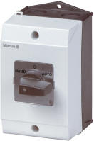
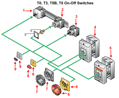
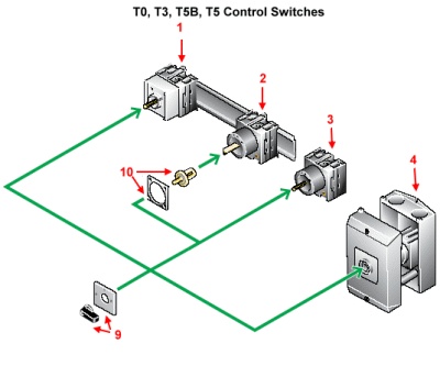
Service
distribution board mounting
(.../IVS) 1 Front IP30 For snap fitting to EN 50022 top-hat rail Flush mounting – Service distribution boards: up to 3 contact units (45 mm mounting depth) – Control panels: up to 11 contact units |
Rear mounting
(.../Z) 2
Front IP65 Secured by screw fixing or snap fitting (T0 or T3) For snap fitting to EN 50022 top-hat rail Coupling drive in door or cover Connection from the front Rear mounting main switches (.../V/SVB) 2 Front IP65 According to IEC/EN 60204 and IEC/EN 60947-3, for T0... up to 8 and for T3... up to 12 current paths With door interlock in the On position |
|
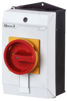
Flush mounting
(.../E) 3
Front IP65 Fitting and connection from the rear Terminal: Pozidriv plus-minus screw Finger- and back-of-hand proof Type T8 with extension terminals as standard Flush mounting main switches (.../EA/SVB) 3 Front IP65 According to IEC/EN 60204 and IEC/EN 60947-3, for T0... up to 8 and for T3... up to 12 current paths N terminal and PE terminal Centre mounting (.../EZ) 3 Front IP65 Mounting in ∅ 22.3 fixing hole according to IEC/EN 60947-5-1 “One-man installation” through centre fixing |
Surface mounting
(.../I...) 4
IP65 With an additional terminal Enclosures for metric cable glands according to EN 50262 Surface mounting main switches (.../I...) 4 IP65 According to IEC/EN 60204 and IEC/EN 60947-3, for T0... up to 8 and for T3... up to 10 current paths Lockable in 0 position with 3 padlocks Enclosures for metric cable glands according to EN 50262 With an additional terminal |
|
Safety switch
(.../I...) 5
IP65 With an additional terminal With cover fuse in the 0 position Lockable in 0 position with 3 padlocks Enclosures for metric cable glands according to EN 50262 With “Safety Switch” label Colour: orange in Switzerland: according to SUVA Directive |
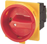
Main switch
(assembly kit)
for use as Emergency-Stop device 6 According to IEC/EN 60204-1 With red rotary handle and yellow locking collar Lockable in 0 position |
|
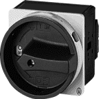
Main switch
(assembly kit) 7
Black rotary handle and locking collar Lockable in the 0 (Off) position |
Thumb-grip
for use as Emergency-Stop device 8 According to IEC/EN 60204-1 Red thumb-grip with yellow front plate |
|
Thumb-grip 9
Black thumb-grip with front plate |
Coupling drive 10
Includes push-fit shaft For retrofitting T0(T3)-.../XZ basic switches for rear mounting Spare parts for T0(T3)/(P1)-.../Z For retrofit conversion of T5(B)-.../E flush mounting switches for rear mounting Spare part for T5(B)-.../Z |