Searching...
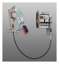
Flange-mounted handle mechanisms mount on the flange of an enclosure door. The Flex Shaft is an extra heavy-duty mechanism that includes a flexible shaft in various lengths, 3 feet (0.9m) through 10 feet (3m) for use with various size enclosures.
The Flex Shaft handle will accept up to three padlock shackles, each with a maximum diameter of 3/8 inches (9.5 mm). It can be used with Type12 fabricated enclosures. An optional handle is available for Flex Shaft that is suitable for use with Type 4 environments.
Flex Shaft comes preset from the factory, requiring only minor field adjustments on installation, which takes about 10 minutes—a significant time savings compared to installation of other types of flange handle mechanisms. The Flex Shaft mechanism also takes up less interior enclosure space than competitive designs, and the handle fits standard flange cutouts. Flex Shaft handle can be remotely mounted from breaker, where an operator can use it by “funneling” the cable through conduit.
Flex Shaft is UL listed under
File E64983 and meets CSA requirements.
Note: Type 4X handle mechanisms are available. Add Suffix X to the complete Part Number.
Note: When selecting the length of shaft, ensure minimum bending radius of 4 inches (101.6 mm) is maintained to operate properly.
Note: The standard method of shipment includes the mechanism preset at the factory; however, minor field adjustments may be required.
|
Breaker
Frame |
Flexible Shaft Length in Feet (m) | |||||||
| 3 (0.9) | 4 (1.2) | 5 (1.5) | 6 (1.8) | 7 (2.1) | 8 (2.4) | 9 (2.7) | 10 (3.0) | |
| G (1) | F0S03C | F0S04C | F0S05C | F0S06C | — | — | — | — |
| F | F1S03C | F1S04C | F1S05C | F1S06C | F1S07C | F1S08C | F1S09C | F1S10C |
| F (dual) | F1S03CD | F1S04CD | F1S05CD | F1S06CD | F1S07CD | F1S08CD | F1S09CD | F1S10CD |
| J | F2S03C | F2S04C | F2S05C | F2S06C | F2S07C | F2S08C | F2S09C | F2S10C |
| K | F3S03C | F3S04C | F3S05C | F3S06C | F3S07C | F3S08C | F3S09C | F3S10C |
| L and MDL | — | F4S04C | F4S05C | F4S06C | — | — | — | F4S10C |
| N | — | F5S04C | F5S05C | F5S06C | — | — | — | F5S10C |
| R | — | F6S04 | F6S05 | F6S06 | — | — | — | — |
| MD, MDS (old) | — | F7S04 | F7S05 | F7S06 | — | — | — | F7S10C |
|
Frame
Size |
Variable Depth
Mounting Range Min./Max. (2)(3) |
Operating
Mechanism Only (4) |
Operating Mechanism w/ 4-Inch Handle | |
|
For NEMA 1—12
Enclosure |
For NEMA 4/4X
Enclosure |
|||
| 150 | 6.50—16 (165.1—406.4) | C371E | C371E1 | C371E2 |
| 250 | 6.50—16.63 (165.1—422.4) | C371F | C371F5 | C371F6 |
| 400 | 6.50—16.63 (165.1—422.4) | C371F | C371F5 | C371F6 |
| 600 | 8.50—22 (215.9—558.8) | C371G | C371G5 | C371G6 |
| 800 | 8.75—22 (222.3—558.8) | C371K | C371K5 | C371K6 |
| 1200 | 9.75—22 (247.7—558.8) | C371K | C371K5 | C371K6 |
NOTES:
(1) Suitable for GC/GD MCCB; not suitable for GMCP.
(2) For increased maximum allowable depth, see connecting rods
(3) Dimensions shown are from panel flange surface.
(4) Does not include handle.
Type 4/4X handle mechanisms are available. Add Suffix X to complete catalog number. Add Suffix I to complete catalog number for IEC handle. Original narrow handle design (No C Suffix) is available. Remove C from catalog number.
When selecting the length of shaft, ensure minimum bending radius of 4 inches (101.6 mm) (5 inches, 12.7 mm for L-, N- and R-Frames) is maintained to operate properly. The standard method of shipment includes the mechanism preset at the factory; however, minor field adjustments may be required.
Dual breakers operator available on F-Frame only. Only the F, J and K can mount LH and RH all other RH only.
|
Circuit Breaker
Frame Size (Amperes) |
NEMA
Enclosure Type |
Operating
Handle Length |
Catalog
Number |
| 150 | 1/3R/3/12 | 4.00 (101.6) | C371H1 |
| 4/4X | 4.00 (101.6) | C371H2 | |
| 1/3R/3/12 | 6.00 (152.4) | C371H3 | |
| 4/4X | 6.00 (152.4) | C371H4 | |
| 250—1200 | 1/3R/3/12 | 4.00 (101.6) | C371H5 |
| 4/4X | 4.00 (101.6) | C371H6 | |
| 1/3R/3/12 | 6.00 (152.4) | C371H7 | |
| 4/4X | 6.00 (152.4) | C371H8 |
For use to prevent bending of the operating handle mounting surface. This is especially useful when the operating handle is mounted on a channel in a multi-door enclosure.
| Amperes | Part Number |
| 600—1200 | C371CS6 |
| Application | PArt Number |
| Disconnect switches (30, 60, 100, 200A sizes) | C371CS1 |
| Circuit breakers (150, 250, 400A sizes) | C371CS1 |
| Circuit breakers (600, 800, 1200A sizes) | C371CS2 |
NOTE:
(1) Increase maximum allowable depth by 5 inches (127 mm).