Searching...
| Setting Range of Overload Trip Amps | For Use with: | ||
|---|---|---|---|
| 1 - 820 | DILE(E)M To DILM820 |
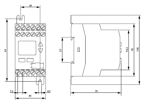
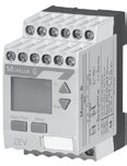
Moeller's ZEV electronic overload relay offers the ultimate motor protection at an economical price. The base unit protects against overloads, phase failure and phase imbalance in motors from 1 to 820A. Thermistor connections and optional ground-fault protection make the ZEV a great choice for virtually all applications where sophisticated, yet economical motor protection is required.
Newly-developed sensor systems and tripping units make the ZEV electronic overload relay the "top-of-the-range" in motor protection. Enhanced tripping classes provide reliable protection for motors with run-up times as long as 40 seconds. Trip classes are selectable from 5 to 40 seconds, allowing precise protection for a range of applications.
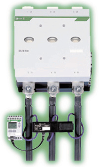
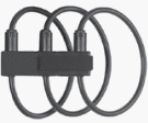
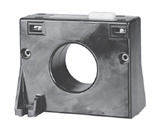
Optional core-balance transformers detect ground faults quickly, while an integrated thermistor connection makes it easy to upgrade to a full motor-protection system.
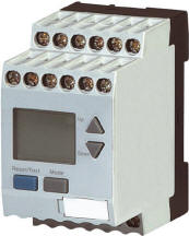
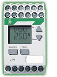
A built-in LCD guides you through set-up and operation. In the event of a fault, the display indicates the origin – speeding the process of troubleshooting and repair. Configurable auxiliary contacts may be added for communication of ground faults, thermistor trips, internal faults or early warning of an overload.
The multi-voltage module automatically adapts to different voltages from 24-240V AC/DC, providing a fast and flexible connection to all conventional control.
Ring-type current sensors make the ZEV a great choice for protection of even small motors. There's no need for main current wiring or back pan drilling. The sensor is installed quickly and easily with hook & loop fasteners. Compared to conventional transformers, this design is up to 58 times smaller, saving valuable space in the control panel.
The ZEV electronic overload relay is touch safe to IP20 specifications. It meets approval standards of UL, CSA, IEC/EN 60 947 and VDE 0660.
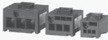
A complete ZEV Electronic Motor Protective Relay consists of:
| Adjustable Setting Range | Length mm | Diameter mm | For use with.. | Part Number | |
|---|---|---|---|---|---|
|
1 – 820 | -- | -- | DILEM DILM7 – DILM820 |
ZEV |
| Adjustable Setting Range | Length mm | Diameter mm | For use with.. | Part Number | |
|---|---|---|---|---|---|
|
1 – 25 | -- | 6 | DILEM; DILM7 – DILM25 | ZEV-XSW-25 |
| 3 – 65 | -- | 13 | DILM32 – DILM50 | ZEV-XSW-65 | |
| 10 – 145 | -- | 21 | DILM65 – DILM115 | ZEV-XSW-145 | |
|
40 – 820 | -- | 110 | DILM185 – DILM820 | ZEV-XSW-820 |
| Adjustable Setting Range | Length mm | Diameter mm | For use with.. | Part Number | |
|---|---|---|---|---|---|
|
|
-- | 200 | -- |
ZEV-XSW-25 ZEV-XSW-65 ZEV-XSW-145 ZEV-XSW-820 |
ZEV-XVK-20 |
| -- | 400 | -- | ZEV-XVK-40 | ||
| -- | 800 | -- | ZEV-XVK-80 |
| Adjustable Setting Range | Length mm | Diameter mm | For use with.. | Part Number | |
|---|---|---|---|---|---|
|
-- | -- | 40 | -- | SSW40-0.3 |
| -- | -- | -- | SSW40-0.5 | ||
| -- | -- | -- | SSW40-1 | ||
| -- | -- | 65 | -- | SSW65-0.5 | |
| -- | -- | -- | SSW65-1 | ||
| -- | -- | 120 | -- | SSW65-120-0.5 | |
| -- | -- | -- | SSW65-120-1 |
| Description | For use with.. | Part Number | |||
|---|---|---|---|---|---|

|
Enables screw mounting of ZEV and Current Sensors to back pan | ZEV ZEV-XSW-25 ZEV-XSW-65 ZEV-XSW-145 |
ZB4-101-GF1 | ||
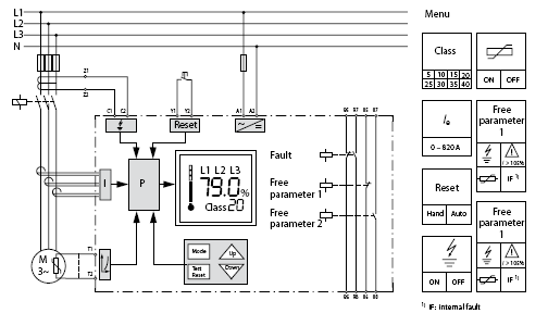
| Inputs | Outputs | ||
|---|---|---|---|
| A 1 / A 2 | Rated control voltage | 95 / 96 | NC contact for overload / thermistor |
| T 1 / T 2 | Thermistor sensor | 97 / 98 | NO contact for overload / thermistor |
| C 1 / C 2 | SSW core-balance transformers | 05 / 06 | NC contact freely assignable |
| Y 1 / Y 2 | Remote reset | 07 / 08 | NO contact freely assignable |
The switchgear is designed for "CLASS 10" in normal and overload operation. To ensure that the switchgear (circuit-breaker and contactor) as well as the cables are not overloaded with extended tripping times, they must be over-dimensioned accordingly. The rated operational current Ie for switchgear and cables can be calculated with the following current factor while taking the tripping class into account:
| Tripping Class | Class 5 | Class 10 | Class 15 | Class 20 | Class 25 | Class 30 | Class 35 | Class 40 |
|---|---|---|---|---|---|---|---|---|
| Current factor for rated operational current Ie | 1.00 | 1.00 | 1.22 | 1.41 | 1.58 | 1.73 | 1.89 | 2.00 |
With the ZEV-XSW-25 to ZEV-XSW-145 push-through sensors, the motor supply leads for each phase are pushed through the respective push-through openings. On motor currents which are less than 1 A, the motor supply leads with the ZEV-XSW-25 are inserted in loops. The number of loops depends on the rated motor current involved.
| Number of Loops n | 4 | 3 | 2 |
|---|---|---|---|
| Rated motor current IN [A] | 0.31 - 0.4 | 0.41 - 0.62 | 0.63 - 1.24 |
| Current settings on relay IE between lowest and highest value [A] | 1.24 - 1.6 | 1.23 - 1.86 | 1.26 - 2.48 |
The current setting IE of the device is calculated as: IE = n x IN
| Class | 5 | 10 | 15 | 20 | 25 | 30 | 35 | 40 |
|---|---|---|---|---|---|---|---|---|
| trecovery after overload trip [min] | 5 | 6 | 7 | 8 | 9 | 10 | 11 | 12 |
| trecovery after test button trip [sec] | 5 | 5 | 5 | 5 | 5 | 5 | 5 | 5 |
| Download | Description |
|---|---|
|
|
ZEV motor-protective system Overload monitoring of motors in EEx e areas |
|
|
Tripping characteristics ZEV 10/00 AWA 2321-1888 Created: 12/4/01 [177 KB] |
|
|
Solid-state motor protection relay ZEV-XSW-... 04/07 AWA 2300-1694 Created: 9/10/04, Modified: 6/8/07 [748 KB] |