| Home | ||
| ||
| ||
| ||
| ||
| ||
| ||
| ||
| ||
| ||
| ||
| ||
| ||
| Reduced Voltage Soft Starters | ||
| ||
| ||
| ||
| ||
| Moeller PDF Archive |
Eaton/Moeller |
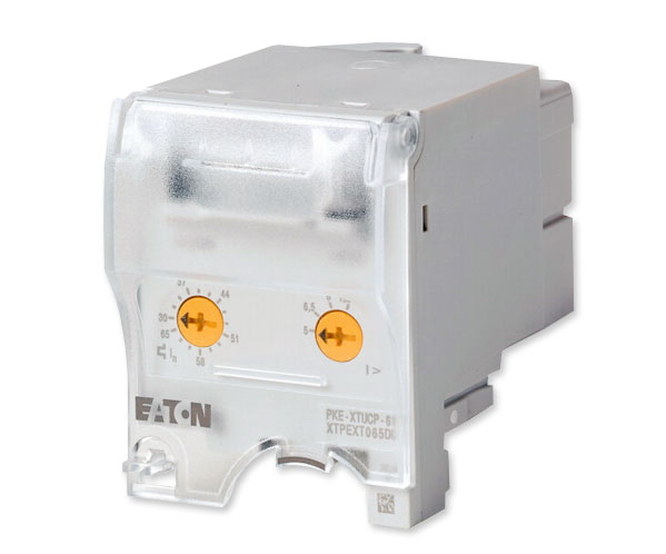
PKE-XTUCP-65 shown |
PKE-XTUCP-65 Trip Block |
|||
| Description | Setting Range Overload Release  |
Old Moeller Part Number |
New Eaton Part Number |
|---|---|---|---|
| Motor-protective circuit-breaker PKE, Coordination type "1" and "2" |
3.0...12.0A | PKE-XTUCP-65 | XTPEXT065DD |
PKE-XTUCP-65 Technical Data |
| Setting range | |||
|---|---|---|---|
| Overload releases |
|||
| Setting range ofoverload releases |
Ir | A | 30 - 65 |
| Overload release, min. | Ir | A | 30 |
| Overload release, max. | Ir | A | 65 |
Short-Circuit Release  |
Irm | A | 150 - 520 |
| Function | with overcurrent protection and short-circuit protective device |
||
| Rated uninterrupted current = rated operational current | Iu = Ie | A | 65 |
| For use with | PKE65 basic device | ||
| Connection to SmartWire-DT | No | ||
| Technical data | |||
|---|---|---|---|
| General | |||
| Standards | IEC/EN 60947, VDE 0660, UL 508, CSA C 22.2 No. 14 |
||
| Climatic proofing | Damp heat, constant, to IEC 60068-2-78 Damp heat, cyclic, to IEC 60068-2-30 |
||
| Ambient temperature °C | |||
| Storage ϑ | °C | -40 - +80 | |
| Open | °C | -20 - +55 | |
| Enclosed | °C | -20 - +40 | |
| Direction of incoming supply | as required | ||
| Degree of protection | |||
| Device | IP20 | ||
| Terminations | IP00 | ||
| Busbar tag shroud to EN 50274 | Finger- and back-of-hand proof | ||
| Mechanical shock resistance half-sinusoidal shock 10 ms to IEC 60068-2-27 |
g | 25 | |
| Altitude | m | Max. 2000 | |
| Main conducting paths | |||
| Rated impulse withstand voltage | Uimp | V AC | 6000 |
| Overvoltage category/pollution degree | III/3 | ||
| Rated operational voltage | Ue | V AC | 690 |
| Rated uninterrupted current = rated operational current |
Iu = Ie | A | 65 |
| Rated frequency | f | Hz | 40 - 60 |
| Maximum operating frequency | Ops./h | ||
| Max. operating frequency | Ops/h | 60 | |
| Trip blocks | |||
| Temperature compensation | °C | -5 - +40 (to IEC/EN 60947, VDE 0660) -25 - +55 (operating range) |
|
| Temperature compensation residual error for T > 40 °C |
± 55 (Arbeitsbereich) | ||
| Setting range of overload releases | 0.25 - 1 x Iu | ||
| Fixed short-circuit release | Trip block 15 x Ir delayed approx. 60 ms |
||
| Short-circuit release tolerance | ± 20% | ||
| Phase-failure sensitivity | yes | ||
| Data for design verification according to IEC/EN 61439 | |||
| Technical data for design verification | |||
| Rated operational current for specified heat dissipation |
In | A | 65 |
| Heat dissipation capacity | Pdiss | W | 0 |
| IEC/EN 61439 design verification | |||
| 10.2 Strength of materials and parts | |||
| 10.2.2 Corrosion resistance | Meets the product standard's requirements. | ||
| 10.2.3.1 Verification of thermal stability of enclosures |
Meets the product standard's requirements. | ||
| 10.2.3.2 Verification of resistance of insulating materials to normal heat |
Meets the product standard's requirements. | ||
| 10.2.3.3 Verification of resistance of insulating materials to abnormal heat and fire due to internal electric effects |
Meets the product standard's requirements. | ||
| 10.2.4 Resistance to ultra-violet (UV) radiation |
Meets the product standard's requirements. | ||
| 10.2.5 Lifting | Does not apply, since the entire switchgear needs to be evaluated. |
||
| 10.2.6 Mechanical impact | Does not apply, since the entire switchgear needs to be evaluated. |
||
| 10.2.7 Inscriptions | Meets the product standard's requirements. | ||
| 10.3 Degree of protection of ASSEMBLIES | Does not apply, since the entire switchgear needs to be evaluated. |
||
| 10.4 Clearances and creepage distances | Meets the product standard's requirements. | ||
| 10.5 Protection against electric shock | Does not apply, since the entire switchgear needs to be evaluated. |
||
| 10.6 Incorporation of switching devices and components |
Does not apply, since the entire switchgear needs to be evaluated. |
||
| 10.7 Internal electrical circuits and connections |
Is the panel builder's responsibility. | ||
| 10.8 Connections for external conductors |
Is the panel builder's responsibility. | ||
| 10.9 Insulation properties | |||
| 10.9.2 Power-frequency electric strength | Is the panel builder's responsibility. | ||
| 10.9.3 Impulse withstand voltage | Is the panel builder's responsibility. | ||
| 10.9.4 Testing of enclosures made of insulating material |
Is the panel builder's responsibility. | ||
| 10.10 Temperature rise | The panel builder is responsible for the temperature rise calculation. Eaton will provide heat dissipation data for the devices. |
||
| 10.11 Short-circuit rating | Is the panel builder's responsibility. The specifications for the switchgear must be observed. |
||
| 10.12 Electromagnetic compatibility | Is the panel builder's responsibility. The specifications for the switchgear must be observed. |
||
| 10.13 Mechanical function | The device meets the requirements, provided the information in the instruction leaflet (IL) is observed. |
||
| Technical data ETIM 5.0 | |||
| Low-voltage industrial components (EG000017) / Tripping bloc for power circuit-breaker (EC000617) |
|||
| Electric engineering, automation, process control engineering / Low-voltage switch technology / Circuit breaker (LV < 1 kV) / Releasing block for circuit breakers (ecl@ss8-27-37-04-10 [AKF008009]) |
|||
| Setting range overload protector | A | 30 - 65 | |
| Initial value of the undelayed short-circuit release - setting range |
A | 0 | |
| End value adjustment range undelayed short-circuit release |
A | 0 | |
| Rated permanent current Iu | A | 65 | |
| Number of poles | — | 3 | |
| Short-circuit release function | — | Delayed | |