| Home | ||
| ||
| ||
| ||
| ||
| ||
| ||
| ||
| ||
| ||
| ||
| ||
| ||
| Reduced Voltage Soft Starters | ||
| ||
| ||
| ||
| ||
| Moeller PDF Archive |
Eaton/Moeller |
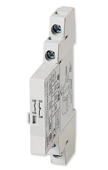
 NHI11-PKZ0 shown |
NHI12-PKZ0 Side Mounted Auxiliary Contact |
||||
| Description | Contacts | For Use With | Old Moeller Part Number |
New Eaton Part Number |
|---|---|---|---|---|
| Standard Side Mounted Auxiliary Contact |
1 N.O. 2 N.C. |
PKZM01 PKZM0 PKZM4 PKZM0-T PKM0 PKE |
NHI12-PKZ0 | XTPAXSA12 |
 |
|
NHI12-PKZ0 Technical Data |
|
| General | |
|---|---|
| Moeller Part No. | NHI12-PKZ0 |
| Eaton Part No. | XTPAXSA12 |
| Delivery program | |
| Product range | Standard auxiliary contact |
| For use with | PKZ0(4) standard auxiliary contacts |
| Contacts | |
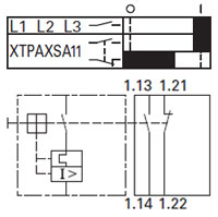
| N/O = Normally open | 1 N.O. |
| N/C = Normally closed | 2 N.C. |
| Connection technique | Screw terminals |
| For use with | PKZM01 PKZM0 PKZM4 PKZM0-T PKM0 PKE |
| Notes: Can be fitted to the right of motor-protective circuit-breakers, transformer-protective circuit-breakers, motor-protective circuit-breakers for starter combinations. Can be combined with: AGM, NHI-E-... trip-indicating auxiliary contact |
|
| Technical data | |
| Auxiliary contacts | |
| Rated impulse withstand voltage (Uimp) | 6000 |
| Overvoltage category/pollution degree | III/3 |
| Rated operational voltage (Ue) | 500 V AC |
| 250 V DC | |
| Safe isolation to EN 61140 Between auxiliary contacts and main contacts |
690 V AC |
| Rated operational current AC-15 | |
| 220 - 240 V | 3.5 A |
| 380 - 415 V | 2 A |
| 440 V 500 V | 1 A |
| Rated operational current DC-13 L/R - 100 ms | |
| 24 V | 2 A |
| 60 V | 1.5 A |
| 110 V | 1 A |
| 220 V | 0.25 A |
| Lifespan, mechanical (Operations) | > 0.1 |
| Lifespan, electrical (Operations) | 0.05 |
| Control circuit reliability (Failure rate) | <10-8, one failure at 100 million operations (at Ue = 24 V DC, Umin = 17 V, Imin = 5.4 mA) |
| interlocked opposing contacts | yes |
| Short-circuit rating without welding | |
| Fuseless (Type) | FAZ-B4/1-HI |
| Fuse (A gG/gL) | 10 |
| Terminal capacities | |
| Solid or flexible conductor, with ferrule | 0,75 - 2,5 |
| Solid or stranded | 18 - 14 |
| Design verification as per IEC/EN 61439 | |
| Technical data for design verification | |
| Rated operational current for specified heat dissipation |
3.5 A |
| Heat dissipation per pole, current-dependent |
0.04 W |
| Heat dissipation capacity | 0 W |
| IEC/EN 61439 design verification | |
| 10.2 Strength of materials and parts | |
| 10.2.2 Corrosion resistance | Meets the product standard's requirements. |
| 10.2.3.1 Verification of thermal stability of enclosures |
Meets the product standard's requirements. |
| 10.2.3.2 Verification of resistance of insulating materials to normal heat |
Meets the product standard's requirements. |
| 10.2.3.3 Verification of resistance of insulating materials to abnormal heat and fire due to internal electric effects |
Meets the product standard's requirements. |
| 10.2.4 Resistance to ultra-violet (UV) radiation | Meets the product standard's requirements. |
| 10.2.5 Lifting | Does not apply, since the entire switchgear needs to be evaluated. |
| 10.2.6 Mechanical impact | Does not apply, since the entire switchgear needs to be evaluated. |
| 10.2.7 Inscriptions | Meets the product standard's requirements. |
| 10.3 Degree of protection of ASSEMBLIES | Does not apply, since the entire switchgear needs to be evaluated. |
| 10.4 Clearances and creepage distances | Meets the product standard's requirements. |
| 10.5 Protection against electric shock | Does not apply, since the entire switchgear needs to be evaluated. |
| 10.6 Incorporation of switching devices and components |
Does not apply, since the entire switchgear needs to be evaluated. |
| 10.7 Internal electrical circuits and connections |
Is the panel builder's responsibility. |
| 10.8 Connections for external conductors | Is the panel builder's responsibility. |
| 10.9 Insulation properties | |
| 10.9.2 Power-frequency electric strength | Is the panel builder's responsibility. |
| 10.9.3 Impulse withstand voltage | Is the panel builder's responsibility. |
| 10.9.4 Testing of enclosures made of insulating material |
Is the panel builder's responsibility. |
| 10.10 Temperature rise | The panel builder is responsible for the temperature rise calculation. Eaton will provide heat dissipation data for the devices. |
| 10.11 Short-circuit rating | Is the panel builder's responsibility. The specifications for the switchgear must be observed. |
| 10.12 Electromagnetic compatibility | Is the panel builder's responsibility. The specifications for the switchgear must be observed. |
| 10.13 Mechanical function | The device meets the requirements, provided the information in the instruction leaflet (IL) is observed. |
| Technical data ETIM 5.0 | |
| Low-voltage industrial components (EG000017) / Auxiliary contact block (EC000041) | |
| Electric engineering, automation, process control engineering / Low-voltage switch technology / Component for low-voltage switching technology / Auxiliary switch block (ecl@ss8-27-37-13-02 [AKN342009]) |
|
| Number of contacts as change-over contact | 0 |
| Number of contacts as normally open contact | 1 |
| Number of contacts as normally closed contact | 1 |
| Rated operation current Ie at AC-15, 230 V | 3.5 A |
| Type of electric connection | Screw connection |
| Mounting method | Side mounting |
| Approvals | |
| Product Standards | UL 508; CSA-C22.2 No. 14; IEC60947-4-1; CE marking |
| UL File No. | E36332 |
| UL Category Control No. | NLRV |
| CSA File No. | 165628 |
| CSA Class No. | 3211-05 |
| North America Certification | UL listed, CSA certified |
| Specially designed for North America | No |
NHI12-PKZ0 Dimensions |
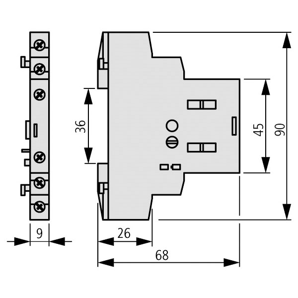 |