hp & kW Ratings - 10 Second Ramp, One Start per Hour,
|
||||||||||||||||||||||||||||||||||||||||||||||||||||||||||||||||||||||||||||||||||||||||||||||||||||||||||||||||||||||||||||||||||||||||||||||||||||||||||||||||||||||||||||||||||||||||||||||||||||||||||||||||||||||||||||||||||||||||||||||||||||||||||||||||||||||||||||||||||||||||||||||||||||||||||||||||||||||||||||||||||||||||||||||||||||||||||||||||||||||||||||||||||||||||||||||||
| Motor Power (hp) |
Motor Power (kW) |
Maximum Allowable Breaker Size |
Maximum Allowable Fuse Size |
|||||
|---|---|---|---|---|---|---|---|---|
| Rated Current (A) |
200 V | 230 V | 480 V | Rated Current (A) |
230 V | 400 V | ||
| 156 | 50 | 60 | 125 | 160 | 45 | 90 | HLD3450 | 500A Class RK5 |
hp & kW Ratings - 10 Second Ramp, One Start per Hour,
400% Current Limit at 40°C
| Motor Power (hp) |
Motor Power (kW) |
Maximum Allowable Breaker Size |
Maximum Allowable Fuse Size |
|||||
|---|---|---|---|---|---|---|---|---|
| Rated Current (A) |
200 V | 230 V | 480 V | Rated Current (A) |
230 V | 400 V | ||
| 96 | 30 | 40 | 75 | 106 | 30 | 55 | HLD3450 | 500A Class RK5 |
Recommended Possible Motor Protection Units
| XTOE Overload | C440 Overload |
|---|---|
| XTOB160LC1 | C440A1A005SAX |
DS7-34DSX160N0-D Specifications |
|---|
| Rated Control Circuit | Part Number | |||
|---|---|---|---|---|
| 24 Vac/Vdc 110/230 Vac 24 Vdc |
DS7-340SX100N0-N DS7-342SX100N0-N DS7-34DSX100N0-D |
DS7-340SX135N0-N DS7-342SX135N0-N DS7-34DSX135N0-D |
DS7-340SX160N0-N DS7-342SX160N0-N DS7-34DSX160N0-D |
DS7-340SX200N0-N DS7-342SX200N0-N DS7-34DSX200N0-D |
| General | ||||
| Standards | IEC/EN 60947-4-2; GB14048.6; UL508; CSA-C22.2 No 0-M91; CSA-C22.2 No 14-05 CE marking |
IEC/EN 60947-4-2; GB14048.6; UL508; CSA-C22.2 No 0-M91; CSA-C22.2 No 14-05 CE marking |
IEC/EN 60947-4-2; GB14048.6; UL508; CSA-C22.2 No 0-M91; CSA-C22.2 No 14-05 CE marking |
IEC/EN 60947-4-2; GB14048.6; UL508; CSA-C22.2 No 0-M91; CSA-C22.2 No 14-05 CE marking |
| Certifications marking |
UL/CE/CSA/C-Tick | UL/CE/CSA/C-Tick | UL/CE/CSA/C-Tick | UL/CE/CSA/C-Tick |
| Ambient temperature (operation) °C |
0 to 40 °C, above 40 °C de-rate linearly by 1% of rated current per Celsius to 60 °C –40 to +40 °C for low temperature version |
0 to 40 °C, above 40 °C de-rate linearly by 1% of rated current per Celsius to 60 °C –40 to +40 °C for low temperature version |
0 to 40 °C, above 40 °C de-rate linearly by 1% of rated current per Celsius to 60 °C –40 to +40 °C for low temperature version |
0 to 40 °C, above 40 °C de-rate linearly by 1% of rated current per Celsius to 60 °C –40 to +40 °C for low temperature version |
| Ambient temperature (storage) °C |
–25 to 55 °C | –25 to 55 °C | –25 to 55 °C | –25 to 55 °C |
| Altitude | 0–1000m, above 1000m de-rate linearly by 2.5% of rated current per 100m to a maximum of 2000m |
0–1000m, above 1000m de-rate linearly by 2.5% of rated current per 100m to a maximum of 2000m |
0–1000m, above 1000m de-rate linearly by 2.5% of rated current per 100m to a maximum of 2000m |
0–1000m, above 1000m de-rate linearly by 2.5% of rated current per 100m to a maximum of 2000m |
| Installation | Vertical | Vertical | Vertical | Vertical |
| Protection class | IP20 | IP20 | IP20 | IP20 |
| Protection class applies to the front and operator control and display elements. Protection type from all sides is IP00. |
With optional covers from the NZM range, protection type IP40 from all sides can be achieved |
With optional covers from the NZM range, protection type IP40 from all sides can be achieved |
With optional covers from the NZM range, protection type IP40 from all sides can be achieved |
With optional covers from the NZM range, protection type IP40 from all sides can be achieved |
| Busbar tag shroud | Back of hand and finger-proof (from front face) |
Back of hand and finger-proof (from front face) |
Back of hand and finger-proof (from front face) |
Back of hand and finger-proof (from front face) |
| Overvoltage category/ pollution degree |
II/2 | II/2 | II/2 | II/2 |
| Shock resistance | 8g/11ms | 8g/11ms | 8g/11ms | 8g/11ms |
| Vibration resistance according to EN 60721-3-2 |
2M2 | 2M2 | 2M2 | 2M2 |
| Mean heat dissipation at rated duty cycle (W) |
25 | 24 | 30 | 42 |
| Radio interference | B | B | B | B |
| Main Circuit | ||||
| Rated operational voltage (V) |
230–460 Vac | 230–460 Vac | 230–460 Vac | 230–460 Vac |
| Mains frequency (Hz) | 50/60 Hz | 50/60 Hz | 50/60 Hz | 50/60 Hz |
| Rated operation current AC 53 (Ie) |
100 | 135 | 160 | 200 |
| Motor Power Ratings | ||||
| 200 V (hp) | 30 | 40 | 50 | 60 |
| 230 V (hp) | 30 | 50 | 60 | 75 |
| 480 V (hp) | 75 | 100 | 125 | 150 |
| 230 V (kW) | 30 | 30 | 45 | 55 |
| 400 V (kW) | 55 | 75 | 90 | 110 |
| Overload cycle according to EN 60947-4-2 |
100A: AC53a; 3-5; 75-10 | 135A: AC53a; 3-5; 75-10 | 160A: AC53a; 3-5; 75-10 | 200A: AC53a; 3-5; 75-10 |
| Wire Specifications | ||||
| Power terminals Single conductor—solid or stranded (AWG) |
12–2/0 | 12–350 kcmil | 12–350 kcmil | 12–350 kcmil |
| Terminal torque (lb-in) |
53–80 | 44–123 | 44–123 | 44–123 |
| Control signals Single conductor—solid or stranded (AWG) |
18–10 | 18–10 | 18–10 | 18–10 |
| Terminal torque (lb-in) | 11 | 11 | 11 | 11 |
| Power Section | ||||
| Rated impulse withstand voltage (Uimp 1.2/ 50 s) |
4 kV | 4 kV | 4 kV | 4 kV |
| Rated insulation voltage | 500 | 500 | 500 | 500 |
| Control Commands—Vac/Vdc | ||||
| Supply voltage control board Us nominal (Vac/Vdc) |
20.4–26.4 | 20.4–26.4 | 20.4–26.4 | 20.4–26.4 |
| Current consumption at 24 Vac/Vdc (mA) | 65 | 65 | 65 | 65 |
| Pick-up voltage | +17.3–+27 | +17.3–+27 | +17.3–+27 | +17.3–+27 |
| Drop-out voltage | +3–0 | +3–0 | +3–0 | +3–0 |
| Relay Outputs | ||||
| Number of relays | 2(TOR) | 2 (TOR) | 2 (TOR) | 2 (TOR) |
| Maximum voltage (Vac) | 250 | 250 | 250 | 250 |
| Maximum current (A) | 1A | 1A | 1A | 1A |
| Soft Start Functions | ||||
| Start ramp (s) | 1–30 | 1–30 | 1–30 | 1–30 |
| Stop ramp (s) | 0–30 | 0–30 | 0–30 | 0–30 |
| Initial voltage % line voltage DS7-342… |
30–92% | 30–92% | 30–92% | 30–92% |
| Initial voltage % line voltage DS7-340… |
30–100% | 30–100% | 30–100% | 30–100% |
| Initial voltage % line voltage DS7-34D… |
30–92% | 30–92% | 30–92% | 30–92% |
| Control Commands—Vac | ||||
| Supply voltage control board Us nominal (Vac) |
102–253 | 102–253 | 102–253 | 102–253 |
| Current consumption at 24 Vac/Vdc (mA) | 14 | 14 | 14 | 14 |
| Pick-up voltage (Vac) | 102–230 | 102–230 | 102–230 | 102–230 |
| Drop-out voltage (Vac) | 0–28 | 0–28 | 0–28 | 0–28 |
| Relay Outputs | ||||
| Number of relays | 2 (TOR) | 2 (TOR) | 2 (TOR) | 2 (TOR) |
| Maximum voltage (Vac) | 250 | 250 | 250 | 250 |
| Maximum current (A) | 3A | 3A | 3A | 3A |
| Soft Start Functions | ||||
| Start ramp (s) | 1–30 | 1–30 | 1–30 | 1–30 |
| Stop ramp (s) | 0–30 | 0–30 | 0–30 | 0–30 |
| Initial voltage % line voltage | 30–92% | 30–92% | 30–92% | 30–92% |
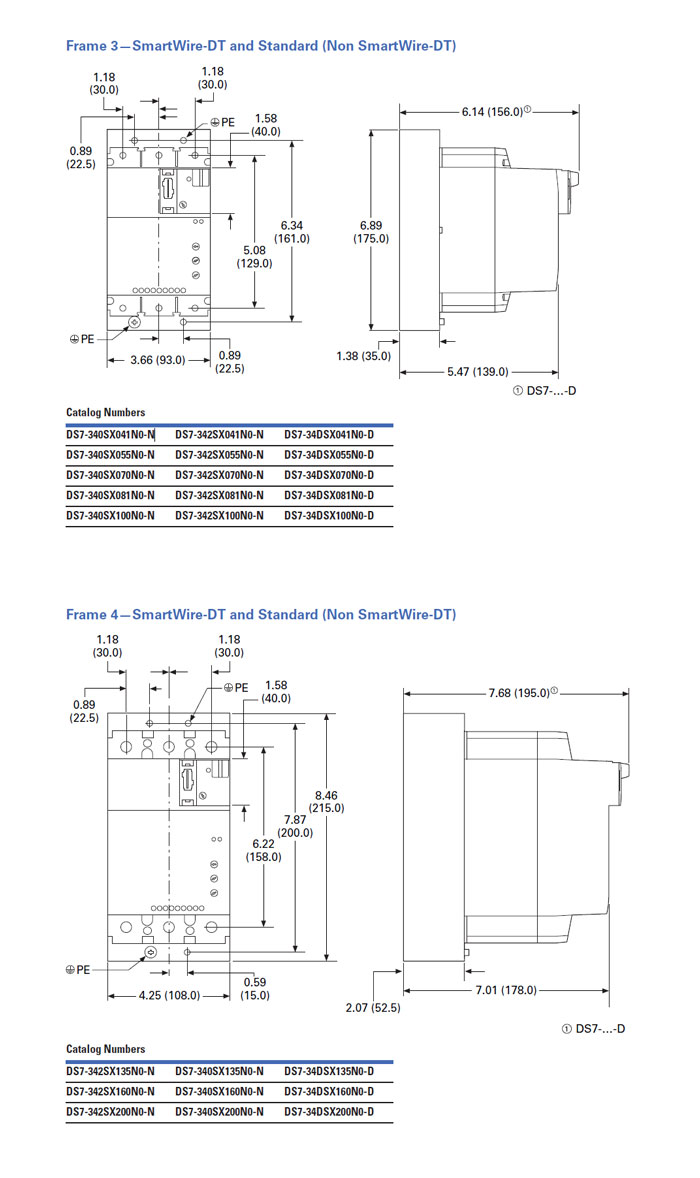
DS7-34DSX160N0-D Dimensions |
|---|
 |
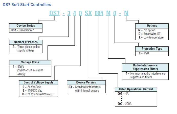
DS7 Part Number Selection Guide |
|---|
 |

