| Eaton Molded Case Circuit Breaker Home | ||
| Digitrip RMS Trip Units | ||
| ||
| ||
| ||
| Metering & Communications | ||
| ||
|
Eaton
|
|
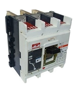 |
Series-C Frame Size - R Part Index CLICK HERE |
Type R (3-Pole) Shown |
|
CRDC320T91W — 100% Rated Digitrip RMS 910 Circuit Breakers
| Number of Poles |
Amperes | Interrupting Capacity |
Terminals |
|---|---|---|---|
| 3 | 2000 | High 600 Vac Rated 100 kAIC at 480 Vac Digitrip RMS 510+ LI* |
None |
* Digitrip KEY:
L – Adjustable Long Delay Pickup (By Adjustable Rating Plug)
S – Adjustable Short Delay Pickup with Fixed Short Delay Time (I2t Response) or Adjustable Short Delay Time (Flat Response)
I – Adjustable Instantaneous Pickup by Setting Short Delay Time to Instantaneous
G – Adjustable Ground Fault Pickup with Adjustable Ground Fault Delay (Flat Response)
Quick Reference Guide
| UL 489/CSA Interrupting Capacity Ratings(1) | |||||
| Circuit Breaker Type |
Number of Poles |
Interrupting Capacity (kA
Symmetrical Amperes) Volts AC (50/60 Hz) |
|||
|---|---|---|---|---|---|
| 240 | 277 | 480 | 600 | ||
| RD | 3, 4 | 125 | — | 65 | 50 |
| CRD(2) | 3 | 125 | — | 65 | 50 |
| RDC | 3, 4 | 200 | — | 100 | 65 |
| CRDC(2) | 3 | 200 | — | 100 | 65 |
| IEC 947-2 Interrupting Capacity Ratings(1) | ||||
| Circuit Breaker Type |
Number of Poles |
Interrupting Capacity (kA
Symmetrical Amperes) Volts AC (50/60 Hz) |
||
|---|---|---|---|---|
| 240 | 415 | 690 | ||
| RD | ||||
| Icu | 3, 4 | 135 | 70 | 25 |
| Ics | 3, 4 | 100 | 50 | 13 |
| RDC | ||||
| Icu | 3, 4 | 200 | 100 | 35 |
| Ics | 3, 4 | 100 | 50 | 18 |
NOTES:
(1) Utilization Category A circuit breakers.
(2) 100% rated breakers.
Specifications
| Trip Unit Type | Digitrip RMS 510 |
Digitrip RMS 610 |
Digitrip RMS 810 |
Digitrip RMS 910 |
Digitrip OPTIM 1050 |
|---|---|---|---|---|---|
| rms sensing | Yes | Yes | Yes | Yes | Yes |
| Breaker Type | |||||
| Frame | R | R | R | R | R |
| Ampere range | 800–2500A | 800–2500A | 800–2500A | 800–2500A | 800–2500A |
| Interrupting rating at 480 volts |
65, 100 (kA) | 65, 100 (kA) | 65, 100 (kA) | 65, 100 (kA) | 65, 100 (kA) |
| Protection | |||||
| Ordering options | LI, LS, LSI, LIG, LSG, LSIG |
LI, LS, LSI, LIG, LSG, LSIG |
LI, LS, LSI, LIG, LSG, LSIG |
LI, LS, LSI, LIG, LSG, LSIG |
LSI(A), LISG |
| Fixed rated plug (In) | Yes | Yes | Yes | Yes | Yes |
| Overtemperature trip | Yes | Yes | Yes | Yes | Yes |
| Long Delay Protection (L) | |||||
| Adjustable rating plug (In) |
No | No | No | No | No |
| Long delay pickup |
0.5–1.0 x (In) | 0.5–1.0 x (In) | 0.5–1.0 x (In) | 0.5 –1.0 x (In) | 0.4–1.0 x (In) |
| Long delay time I2t |
2–24 seconds | 2–24 seconds | 2–24 seconds | 2–24 seconds | 2–24 seconds |
| Long delay time I4t |
No | No | No | No | 1–5 Seconds |
| Long delay thermal memory |
Yes | Yes | Yes | Yes | Yes |
| High load alarm |
No | 0.85 x Ir | 0.85 x Ir | 0.85 x Ir | 0.5-1.0 x Ir |
| Short Delay Protection (S) | |||||
| Short delay pickup |
200–600% S1 and S2 x (Ir) |
200–600% S1 and S2 x (Ir) |
200–600% S1 and S2 x (Ir) |
200–600% S1 and S2 x (Ir) |
150-800% x (Ir)(1)(2) |
| Short delay time I2t |
100–500 ms | 100–500 ms | 100–500 ms | 100–500 ms | 100–500 ms |
| Short delay time flat |
100–500 ms | 100–500 ms | 100–500 ms | 100–500 ms | 100–500 ms |
| Short delay time zone selective interlocking |
Yes | Yes | Yes | Yes | Yes |
| Instantaneous Protection (I) | |||||
| Instantaneous pickup | 200–600% M1and M2 x (In) |
200–600% M1and M2 x (In) |
200–600% M1and M2 x (In) |
200–600% M1and M2 x (In) |
200–800% x (In)(2) |
| Discriminator | Yes(3) | Yes(3) | Yes(3) | Yes(3) | Yes |
| Instantaneous override | Yes | Yes | Yes | Yes | Yes |
| Ground Fault Protection (G) | |||||
| Ground fault alarm(4) |
No | No | No | No | 25–100% x (In) |
| Ground fault pickup(4) |
25–100% x (Is) | 25-100% x (Is) | 25–100% x (Is) | 25–100% x (Is) | 25–100% x (In) |
| Ground fault delay I2t |
100–500 ms | 100–500 ms | 100–500 ms | 100–500 ms | 100–500 ms |
| Ground fault delay flat |
100–500 ms | 100–500 ms | 100–500 ms | 100–500 ms | 100–500 ms |
| Ground fault zone selective interlocking |
Yes | Yes | Yes | Yes | Yes |
| Ground fault thermal memory |
Yes | Yes | Yes | Yes | Yes |
| System Diagnostics | |||||
| Status LEDs | Yes | Yes | Yes | Yes | Yes |
| Cause of trip LEDs |
Yes | Yes | Yes | Yes | Yes |
| Magnitude of trip information |
No | Yes | Yes | Yes | Yes |
| Remote signal contacts | No | Yes | Yes | Yes | Yes |
| System Monitoring | |||||
| Digital display | No | Yes | Yes | Yes | Yes(5) |
| Current | No | Yes | Yes | Yes | Yes |
| Voltage | No | No | No | Yes | No |
| Power and energy |
No | No | Yes | Yes | Yes |
| Power quality—harmonics | No | No | No | Yes | Yes |
| Power factor |
No | No | Yes (over Eaton PowerNet only) |
Yes | Yes |
| Communications | |||||
| Eaton PowerNet |
No | No | Yes | Yes | Yes |
| Testing | |||||
| Testing method | Integral | Integral | Integral | Integral | OPTIMizer, BIM, PowerNet |
NOTES: |
Notes: |
CRDC320T91W Dimensions
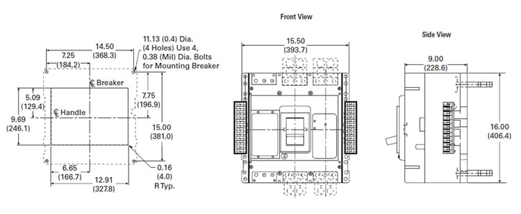 |
| Number of Poles | Width | Height | Depth |
|---|---|---|---|
| 3 | 15.50 (393.7) | 16.00 (406.4) | 9.75 (247.7) |
| 4 | 20.00 (508.0) | 16.00 (406.4) | 9.75 (247.7) |